8
PHKSA 18-Li B2
GB
CY
♦
Insert the mains plug into the mains power socket.
The red control LED lights up.
♦
The green control LED indicates that the
charging process is complete and the battery
pack is ready.
♦
Insert the battery pack back into the appli-
ance.
■
Never recharge a battery pack again
immediately after rapid charging. This could
overcharge the battery pack , thus reducing
the lifespan of the battery and charger .
♦
Switch off the charger for at least 15 minutes
between successive charging sessions. Also
disconnect the power plug from the mains
power socket.
Attaching/disconnecting the battery
pack to/from the appliance
Inserting the battery pack:
♦
Allow the battery pack to click into the
handle.
Removing the battery pack:
♦
Press the release button and remove the
battery pack .
Checking the battery charge level
♦
Press the battery charge level button to
check the status of the battery (see also main
diagram). The status/remaining charge will be
shown on the battery display LED as follows:
♦
RED/ORANGE/GREEN = maximum charge/
power
RED/ORANGE = medium charge/power
RED = low charge – charge the battery
Checking the blade guard
♦
Pull back on the release lever for the blade
guard as far as the stop.
The blade guard must move freely without jam-
ming and must spring back into its starting position
automatically when you let go of the release lever
for the blade guard .
Initial use
Fitting/changing the saw blade
Always remove the battery pack before changing
the saw blade !
1. Set the cutting depth (using the locking screw )
to the minimum position, 0 mm.
2. Swing the blade guard back using the
release lever and put the appliance down.
3. Press the spindle lock button (until it engages)
and use the Allen key to release the clamping
screw . Now remove the clamping screw
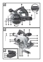
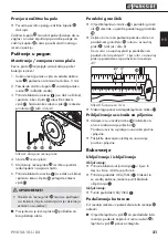
and the clamping flange (see also Fig. A).
Fig. A Changing the saw blade
4. Remove saw blade.
5. Fitting a saw blade is carried out in the reverse
order.
6. Press the spindle lock button (until it engages)
and use the Allen key to tighten the clamping
screw .
WARNING!
►
The arrow on the saw blade must corre-
spond to the arrow showing the direction
of rotation (running direction shown on the
appliance).
■
Ensure that the saw blade is suitable for the
rotational speed of the tool.
Rip fence
♦
Loose the wing screw and insert the rip
fence into the rip fence slot .
♦
Set the desired cut width with the help of the
scale on the rip fence and the cut out in the
base plate (see also Fig. B).
The right-hand recess in the base plate is for a
cutting angle of 0°. The left-hand recess in the
base plate is for a cutting angle of 45°.
Содержание 270420
Страница 3: ...A B C...
Страница 29: ...26 PHKSA 18 Li A1...
Страница 33: ...30 PHKSA 18 Li B2 BG 2 3 a 4 a...
Страница 34: ...31 PHKSA 18 Li B2 BG 5 a 6 a...
Страница 35: ...32 PHKSA 18 Li B2 BG a...
Страница 36: ...33 PHKSA 18 Li B2 BG 8...
Страница 37: ...34 PHKSA 18 Li B2 BG...
Страница 38: ...35 PHKSA 18 Li B2 BG 2 C 10 C 40 C C 15...
Страница 39: ...36 PHKSA 18 Li B2 BG 1 0 mm 2 3 A A 4 5 6 B 0 45 B 3 cm...
Страница 40: ...37 PHKSA 18 Li B2 BG 3 mm 1 2 3 50 80...
Страница 41: ...38 PHKSA 18 Li B2 BG 2012 19 EU 2006 66 3...
Страница 43: ...40 PHKSA 18 Li B2 BG www kompernass com 20 www kompernass com 00800 111 4920 IAN 270420...
Страница 57: ...54 PHKSA 18 Li B2...


