


True Ground Speed Sensor (TGSS) 740
11
Installation
4.1.3.
Mounting the TGSS to a vehicle
It is up to the original equipment manufacturer (OEM) to ensure the product is
securely mounted to the vehicle.
The following guidelines are related to physically attaching the TGSS to the
mounting bracket on a vehicle:
•
The TGSS should be secured with
bolts in all 3 bolt holes
using 6 mm
Hex Head
bolts and locking washers.
The bolts should be tightened to 5.4-7.3 Nm (48-65 in lbs).
Appropriate length bolts are routed from the underside of the unit through the
mounting plate and tightened into the shock absorbers on the unit's base. The bolts
should engage the threads in the shock absorbers to a maximum depth of 6.35 mm
(¼").
4.1.4.
Line of sight clearance
It is important for the sight line of the radar beam to be as unobstructed as possible.
Interference with radar beam can lead to false or erratic speed readings.
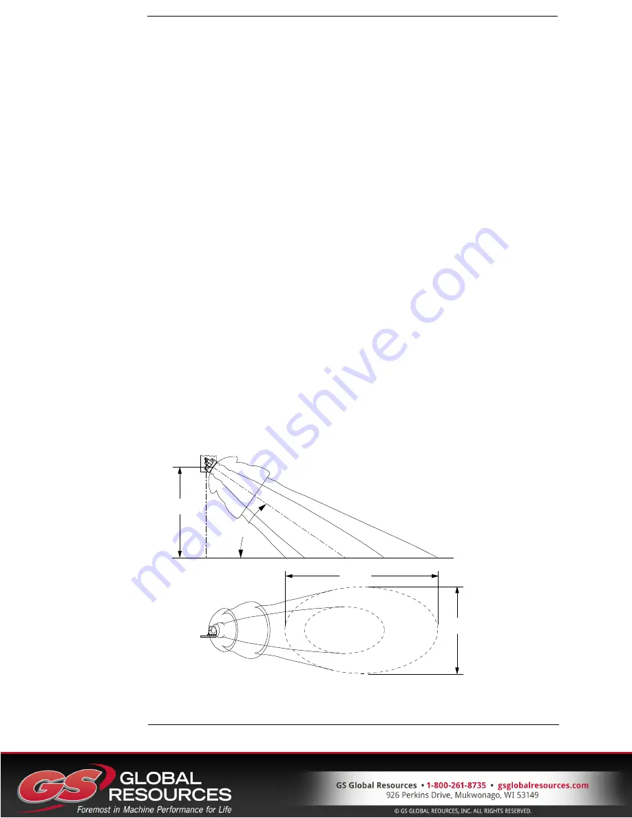
The radar beam pattern is shown in Figure 5: Doppler line of sight. The smaller
region is the -3dB level and the larger region is the -10 dB level. These areas are the
relative sensitivity of the TGSS to motion.
The-3dB region is the area where the TGSS is most sensitive. This path must be clear
of any objects. Interference in this area will have a high likelihood of degrading the
performance of the product's ability to provide accurate speed measurement.
The larger -10dB region is a lower sensitivity area. Objects that interfere in this area
have a potential to be an issue.
35°
1000
959
1697
Figure 6: Doppler line of sight


