Parker EME
PSUP Connections
192-120147N9 PSUP Manual 2019-06
23
Dimensional drawing: LCG-0055-0.45 mH-UL
2.3.6.
Braking resistor / temperature switch PSUP (mains module)
The energy generated during braking operation must be dissipated via a braking
resistor.
Connector X40
Pin
Description
+R
+ Braking resistor
short-circuit proof!
-R
- Braking resistor
PE
PE
T1R
Temperature Switch
T2R
Temperature Switch
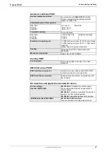
Braking operation PSUPxxD6 (mains module)
Device type
PSUP10
PSUP20
PSUP30
Capacitance / storable
energy
550 µF/
92 Ws at 400 V
53 Ws at 480 V
1175 µF/
197 Ws at 400 V
114 Ws at 480 V
1175 µF/
197 Ws at 400 V
114 Ws at 480 V
Minimum braking-
resistance
27
Ω
15
Ω
10
Ω
Recommended nominal
power rating
500 ... 1500 W
500 ... 3500 W
500 ... 5000 W
Pulse power rating for 1s
22 kW
40 kW
60 kW
Maximum permissible
continuous current
13 A
15 A
15 A
PSUP10: 2400 µF
Maximum capacity in the axis system:
PSUP20 & PSUP30: 5000 µF
100 µF per kW of the temporal medium value of the total power (transmi
power dissipation) in the axis system.
Reference value for the required capacity in an axis system
Example: PSUP20 (1175 µF) with one axis controller (440 µF)
Total power 15 kW, 100 µF/kW => 1500 µF required in the axis system.
Axis system: 1615 µF are sufficient.
Connection of a braking resistor on PSUP (mains module)
Minimum line cross section:
1.5 mm
2
Maximum line length:
2 m
Maximum intermediate circuit voltage:
810 VDC
Switch-on threshold:
780 VDC
Hysteresis
20 VDC


