Parker PSD1-S Скачать руководство пользователя страница 10

Conditions of utilization


10 (20)


192-011004N5 DOC-0002-01-R014 

14.08.17 09:41 


In general, the connection mains filter - device shall be as short as possible. 

unshielded:  < 0.5 m 
shielded: 

< 5 (screen must be connected to ground - e.g. ground-control cabinet) 
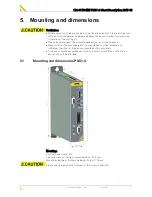
 

3.1.2. 

Motor and feedback cable requirements 


Operation of the devices only with motor and feedback cables whose plugs contain 
a special full surface area screening.   


Maintain the shielding as close as possible to the cable-end (max distance 8 cm). 


Earth empty wires in the cable. 


<100 m per axis (the cable must not be rolled up!). 
PSD1-S 
For motor cables >50 m a motor output choke is required for PSD1-S devices: 


ECM-0005-01 (max. 7 A motor nominal current) 


Shielding connection of 

the motor cable


The cable must be fully-screened and connected to the device housing. Use the 

cable clamps/shield connecting terminals furnished with the device. 
The shield of the cable must also be connected with the motor housing. The fixing 

(via plug or screw in the terminal box) depends on the motor type. 


3.1.3. 

Cable installation: 


Signal lines and power lines should be installed as far apart as possible; cross 

points 90°. 


Signal lines should never pass close to excessive sources of interference (motors, 

transformers, contactors etc.). 


Do not place mains filter output cable parallel to the load cable. 


Lines must lead along conductive, grounded metal surfaces as closely as 
possible. 


3.1.4. 

Motors 

Operation with standard motors. 


3.1.5. 

Protective earth 


Additionally to the ground connection at the power mains connection, establish a 
ground connection via the grounding screw (see on page 16) on the device bottom 

by means of a copper cable with the same section.   
In case there is not earth connection at the mains connection, the wire used must 

have a minimum diameter of 10 mm

2


The connection to the central earth rail should be as short as possible. The 
minimum required width of the central earth rail depends on the length of the 

grounding cable: 


Length [m] 

Width [mm] 

Strength [mm] 

0.5 

20 

40 

1.5 

50 


Pay close attention to the overall grounding of the complete system. 


With several mounting plates: Interconnect several mounting plates using copper 
rails or copper band. 


Pay attention to the ground connection between the control cabinet and machine. 


Earth control transformer thoroughly (for 24 VDC). Use a transformer with a metal 

socket and pay attention to provide for good conductive contact on mounting plate. 


3.1.6. 

Grounding requirements 

Connect the filter housing and the device to the cabinet frame, making sure that the 

contact area is adequate and that the connection has low resistance and low 
inductance by using an 3 mm steel plate (galvanized). 

Never mount the filter housing and the device on paint-coated surfaces! 


Содержание PSD1-S

Страница 1: ...192 011004N5 PSD1 S Short Description 2017 08 192 011004N5 DOC 0002 01 R014 14 08 17 09 41 1 20 192 011004N5 DOC 0002 01 R014 2017 08 Up from release R01 03 PSD1 S Parker Servo Drive Manual ...

Страница 2: ...ions German Master created Production site Germany Parker Hannifin Manufacturing Germany GmbH Co KG Electromechanical Drives Division EME Robert Bosch Strasse 22 77656 Offenburg Germany Tel 49 0781 509 0 Fax 49 0781 509 98176 Internet www parker com eme http www parker com eme E mail EM Motion parker com mailto EM Motion parker com Parker Hannifin GmbH registered office Bielefeld HRB 35489 Managem...

Страница 3: ...Conditions of utilization for UL certification of PSD1 S 11 3 3 EC declaration of conformity PSD1 S 14 4 Connector overview PSD1 S 15 4 1 Front view PSD1 S 15 4 2 View from below PSD1 S 16 4 3 View from above PSD1 S 16 5 Mounting and dimensions 17 5 1 Mounting and dimensions PSD1 S 17 6 Technical Data 18 6 1 Mains connection PSD1 S 18 6 2 Control Voltage 24 VDC PSD1 S 18 7 Index 19 1 What is neces...

Страница 4: ...ent 4 Serial Number 5 Output Voltage 6 Output current 7 Output frequency 8 UL certification corresponding to the existing logo 2 4 Designated use The device is designed for operation in electric power drive systems EN 50178 Motion sequences can be automated with this device Several motion sequences can be can combined by interconnecting several of these devices Mutual interlocking functions must b...

Страница 5: ... This product contains materials that fall under the special disposal regulation from 2010 which corresponds to the EC directory 2008 98 EC for dangerous disposal material We recommend to dispose of the respective materials in accordance with the respectively valid environmental laws The following table states the materials suitable for recycling and the materials which have to be disposed of sepa...

Страница 6: ...the officer responsible for the safety of the system to perform the required task and in the process are capable of recognizing potential hazards and avoiding them definition of technical personnel according to VDE105 or IEC364 who have a knowledge of first aid techniques and the local emergency rescue services who have read and will observe the safety instructions who have read and observe the ma...

Страница 7: ... than 3 5 mA The drive motor must be grounded with a suitable protective lead The devices are equipped with high voltage DC capacitor After switching off the supply voltage it may take up to 3 minutes with additional capacity modules it may take up to 30 minutes to discharge the capacitors Danger of electric shock in case of non respect Do never perform resistance tests with elevated voltages over...

Страница 8: ...red safe In doing so people must not be endangered The here in described technical data processes and circuits are merely a general guidance and may not be suitable for the user s specified application We cannot guaranty the suitability for certain applications of the device described in this manual 2 7 Before commissioning the drive please observe the following Read the safety instructions Make s...

Страница 9: ...for utilization within certain voltage limits 2014 35 EU are fulfilled when the following boundary conditions are observed Operation of devices only in the state in which they are delivered Contact protection mating plug In order to ensure contact protection all mating plugs must be present on the device connections even if they are not wired Instructions for this manual Please respect the specifi...

Страница 10: ...filter output cable parallel to the load cable Lines must lead along conductive grounded metal surfaces as closely as possible 3 1 4 Motors Operation with standard motors 3 1 5 Protective earth Additionally to the ground connection at the power mains connection establish a ground connection via the grounding screw see on page 16 on the device bottom by means of a copper cable with the same section...

Страница 11: ... 2012 C22 2 No 274 13 1st Edition issued March 2013 3 2 2 Installations Environmental Characteristics PSD1 S Risk of Electric Shock wait at least 3 minutes before removing cover Use in Pollution degree 2 Environment Maximum Surrounding Air Temperature 40 C The devices must be appropriately protected e g by a switching cabinet Open type equipment Use 60 75 C wires only Use Copper Conductors Only Do...

Страница 12: ...LP CC 12 12 600 1 phase LP CC 6 6 600 3 phases Alternate External Branch Circuit Protection Device Spezification Time Delay Class CC Fuses Listed Cartridge Fuses Non Renewable manufactured by Mersen USA Newburyport MA LLC E2137 200 kARMS Symmetrical A I C Model No Current Arms Voltage VAC Quantity Phase PSD1 S_1200 ATDR8 8 600 1 phase ATDR3 3 600 3 phases PSD1 S_1300 ATDR12 12 600 1 phase ATDR6 6 ...

Страница 13: ... 1 27 60s 51 Ω 40 W External DBU Ratings Servo Drive Model Nos Max Current Amps Max Duty Cycle per cent Min Resistance D B U Resistor Peak rms Ohm PSD1SW1200 7 84 A 0 15 A 1 91 60s 51 Ω 60 W PSD1SW1300 7 84 A 0 45 A 5 73 60s 51 Ω 180 W 3 2 6 In Output Ratings Input Ratings Servo Drive Model Nos Input Voltage V AC Frequency Phase Maximum Input Current A rms PSD1SW1200 3AC230 VAC 10 50 60 Hz 1 7 PSD...

Страница 14: ...Conditions of utilization 14 20 192 011004N5 DOC 0002 01 R014 14 08 17 09 41 3 3 EC declaration of conformity PSD1 S ...

Страница 15: ...Front view PSD1 S View from above see on page 16 P10 Status LEDs for the fieldbus C11 Slot for SD card SD Card not included in delivery S12 Device address higher value half byte accept with power ON S13 Device address low value half byte accept with power ON P14 Status LED device X17 Digital Inputs outputs S33 For safety option S34 For safety option View from below see on page 16 4 Connector overv...

Страница 16: ...d connection Connect ground via ring cable lug with a 10 mm2 copper cable to central ground Front view see on page 15 4 3 View from above PSD1 S Front view see on page 15 X60 PC Interface to configure and program servo axes X61 Fieldbus Interface output X62 Fieldbus Interface input X63 Terminals AC Mains Supply DC high voltage supply Connection of braking resistor or bridge to activate the interna...

Страница 17: ...ended distances of other devices Make sure that the mounting plate is not exhibited to other temperature influences than that of the devices mounted on this very plate The devices must be mounted vertically on a level surface Make sure that all devices are sufficiently fixed 5 1 Mounting and dimensions PSD1 S Mounting 2 socket head screws M6 Lateral distance of fixing of mounting holes 50 5 mm Mou...

Страница 18: ...mains module Electric current drain 0 5 A Output current of digital output currents fed via connectors X17 2 3 Output current of motor brakes fed via connectors X51 1 2 Current requirements of optional boards 6 3 Size Weight Category Specifications Controller type Weight kg Dimensions Height x Width x Depth mm PSD1 S_1200 1 33 200 x 50 x 180 PSD1 S_1300 6 4 Environmental requirements PSD1 Category...

Страница 19: ...nation of the safety instructions 6 F Frontansicht PSD1 M 15 G General hazards 6 Grounding requirements 10 I In Output Ratings 13 Installations Environmental Characteristics PSD1 S 11 Introduction 4 M Mains connection PSD1 S 18 Mains filter for use in industrial areas 9 Motor and feedback cable requirements 10 Motors 10 Mounting and dimensions 17 Mounting and dimensions PSD1 S 17 N Notes on the us...

Страница 20: ...Index 20 20 192 011004N5 DOC 0002 01 R014 14 08 17 09 41 ...

Отзывы: