


• Choose
Next
to set
RPI
.
• Choose
Finish
. Notice that the PSSCCNA is now under the I/O
configuration.
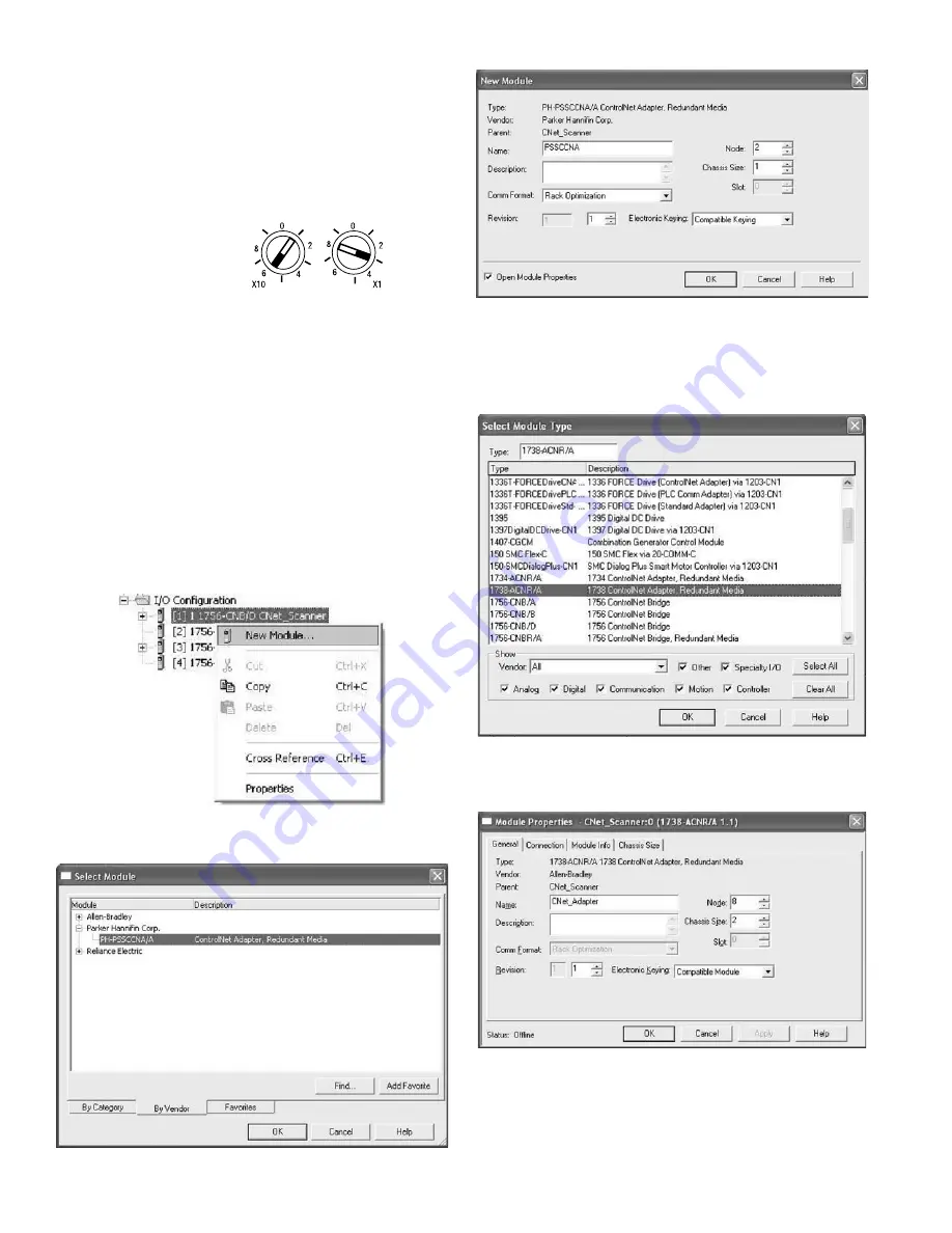
If your RSLogic 5000 is Version 13.X:
• Choose the
1738-ACNR/A
from the list of modules.
• Enter a name, an appropriate node address, and chassis size.
Make sure to choose
Compatible Module for Electronic Keying
setting.
• Choose
Next
to set
RPI.
• Choose
Finish
. Notice that the 1738-ACNR is now under the
I/O configuration
isysNet ControlNet Adapter, Series A (PSSCCNA)
E103P
4
Set the Node Address
To set the node address, adjust the switches on the front of the
module (refer to the illustration on page 1). Use a small blade
screwdriver to rotate the switches. Line up the small notch on the
switch with the number setting you wish to use. The two switches
are most significant digit (MSD) and least significant digit (LSD).
The switches can be set from 01 through 99. The module reads the
switches at power-up only.
The rotary switches are read periodically. If the switches have been
changed since the last time they were read and they no longer match
the on line address, a minor fault will occur, which is indicated by a
flashing red Adapter Status LED.
EDS File Requirements
The EDS file is available online at www.parker.com/pneu/isysNet.
This example shows the
node address set at 63.
Add ControlNet Adapter to RSLogix 5000
I/O Configuration
To add your PSSCCNA to RSLogix 5000 I/O configuration, follow
these steps:
• In RSLogix 5000, highlight the
ControlNet Scanner
, right click
and select
New Module
.
If your RSLogic 5000 is Version 15.X or greater:
• Choose the
PSSCCNA
module from the list of Parker modules.
• Enter a name, an appropriate address and chassis size.


