


12
Parker Hannifin Manufacturing Germany GmbH & Co. KG
Pump & Motor Division Europe
Chemnitz, Germany
Axial Piston Pump
Series PV, series 47 and higher
Bulletin MSG30-3245-INST/UK
Installation manual
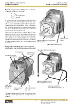
10. Compensator accessories
10.1 Pressure relief pilot valve, code
PVAC1P...
The pressure relief pilot valve code PVAC1P... is
optimally tuned for the requirements of the com-
pensator valves of the series PV. It has a mounting
interface NG6 according to DIN 24340 and can be
mounted directly on top of all compensator valves
with the topside mounting interface.
Such a valve is only necessary for the compensa-
tors with elbow manifold (...MT1 and ...UDR) and
for the versions without integrated pressure pilot
cartridge (compensator code ends with..Z). Al
other versions include an integrated pilot valve.
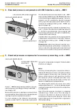
lock nut
set screw
After loosening the lock nut SW13 an adjustment
of the compensating pressure for the pump is
possible in a range of approx. 20 bar up to 350 bar.
The pressure pilot valve is also available with a
DIN lock.
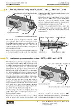
10.2 Multiple pressure pilots PVAC1E...,
PVAC2P..., PVAC2E... und PVAC2M...
For multiple pressure pilots, codes PVAC2P...,
PVAC2E... and PVAC2M... a sandwich valve with
two direct-action pressure cartridge valves is used
to pilot the pump.
Adjustment A: tolerance compensation for opti-
mized performance; done at pilot cartridge.
Adjustment B: maximum pressure setting; done
at integrated pressure pilot valve.
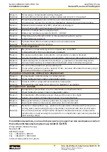
Constant horse power curve with adjustment
At the adjustment screw of the horse power pilot
valve a basic adjustment of the horse power com-
pensator can be made. After loosening the lock
nut (self sealing nut) the compensator control
curve can be moved by turning the adjustment
screw (adjustment A in the diagram left). This
adjustment, done to meet the required constant
input horse power curve, is already made during
the factory test and should be modified only in
exceptional cases.
To adjust the correct constant horse power curve
a measuring device is required. An output power
measurement requires pressure and flow meter-
ing. An input power measurement requires torque
and speed measurement or a measurement of
the electric motor current.
Note:
For horse power control the load sensing
differential is set to 15 ± 1 bar. Any change will
result in a deviation from the horse power setting.
Note
: The setting is very sensitive, 0.1 mm
change of the spindle changes the pressure ap-
proximately 20 bar.