Parker 159456ECD Скачать руководство пользователя страница 16


Parker Hannifin Corporation – UTS User Manual 

11 

7


CAN Information 


SAE J1939 

The J1939 standards come from the international Society of Automotive Engineers (SAE) and were developed to 

provide a standard architecture by which multiple electronic systems on a vehicle can communicate. J1939 has 

been implemented in a broad range of vehicles and transportation systems and provides a reliable 

communication protocol over a high-speed CAN network.  

The UTS uses this protocol to transmit its condition as a predefined set of outputs. All messages are SAE J1939 

Proprietary B PGN's except the address claim request and response. 


Identifier Description 

The J1939 protocol uses a 29-bit identifier. The 29-bit identifier is built up as follows: 


Bit 0-7 is Source Address (

SA


Bit 8-23 is Parameter Group Number (

PGN


Bit 24 is Data Page (

DP


Bit 25 is Reserved (

R


Bit 26-28 is Priority (

P

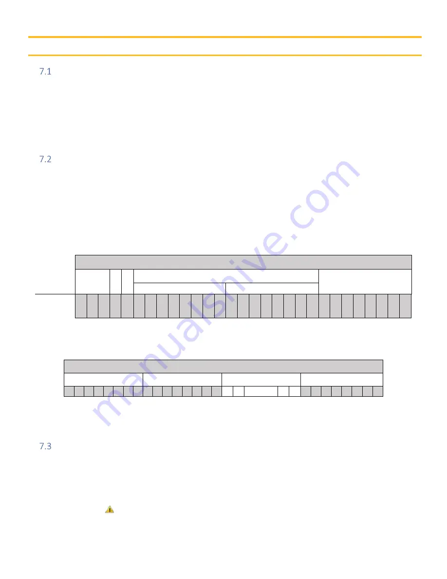
Table 7.2.1: J1939 CAN Identifier Structure 


 29-bit IDENTIFIER


P

riority 

R  DP 

P

arameter 

G

roup 

N

umber 

S

ource 

A

ddress 

PDU Format 

PDU Specific 

CAN 29 Bit 

ID Position  29  28  27  26  25  24  23  22  21  20  19  18  17  16  15  14  13  12  11  10  9  8  7  6  5  4  3  2  1 


Each identifier has an associated 8-byte data field. The data field is built up as shown in Table 7.2.2. 

Table 7.2.2: The Data Field Structure 

DATA FIELD 

BYTE 1 

BYTE 2 

BYTE 3-7 

BYTE 8 

7  6  5  4  3  2  1  0  7  6  5  4  3  2  1  0  7  6 

… 

1  0  7  6  5  4  3  2  1  0 


The Data Field is structured as Little Endian within the bytes, and Big Endian for the Data Field. This is visualized 

in Table 7.2.2 above.  


UTS Communications 

The UTS uses two communication message types: Global and Specific Address. 

o


Global Message: 

This is the operational “Broadcast mode” message for all the axis tilt information on the 

sensor. In these messages the unit broadcasts the outgoing data (status of each axis) on the J1939 bus. 

o


Specific Address Message:

 This is the “Service mode” message for the sensor. In these messages the UTS 

receives write and query messages to its node address from the J1939 bus. 


Ensure there is no loss of power while making programming changes with the UTS in service 

mode 

Содержание 159456ECD

Страница 1: ...Effective June 2019 Supersedes...

Страница 2: ...alysis and testing is solely responsible for making the final selection of the system and components and assuring that all performance endurance maintenance safety and warning requirements of the appl...

Страница 3: ...l ii Publication History The following table provides an overview of the changes made to this document over the course of its publication history Revision Description of Change Rev 001 First release o...

Страница 4: ...racteristics 4 4 Installation Quick Sheets 5 UTS Version 2 5 5 Product Introduction 7 Overview 7 UTS Filtering Description 8 6 Installation Guidelines 9 Operating Conditions 9 CAN 9 Power Supply Requi...

Страница 5: ...ion List 3 Table 3 1 1 Physical and Electrical Characteristics 4 Table 6 3 1 UTS Power Supply Requirements 9 Table 7 2 1 J1939 CAN Identifier Structure 11 Table 7 2 2 The Data Field Structure 11 Table...

Страница 6: ...y Do not use the product if electronic modules cabling or connectors are damaged or if the control system shows error functions Electronic control systems in an inappropriate installation and in combi...

Страница 7: ...y positioned or mounted cabling can be influenced by radio signals which can interfere with the functions of the system Safety During Start Up Danger Risk of death or injury Do not start the machine s...

Страница 8: ...on and service personnel The user of this manual should have basic knowledge in the handling of electronic equipment Terminology The abbreviations and acronyms used in this manual are defined in the f...

Страница 9: ...N protocol SAEJ1939 SAEJ1939 SAEJ1939 CAN messages see part drawing see part drawing see part drawing CAN bus speed 250 kbps 250 kbps 250 kbps Data broadcast rate 10 Hz 50 Hz 50 Hz CAN source address...

Страница 10: ...Parker Hannifin Corporation UTS User Manual 5 4 Installation Quick Sheets UTS Version 2 Figure 4 1 1 UTS Quick Sheet Page 1...

Страница 11: ...Parker Hannifin Corporation UTS User Manual 6 Figure 4 1 2 UTS Quick Sheet Page 2...

Страница 12: ...on the electronics are layered with a conformal coating and the enclosure is sealed against harsh environments using spin weld technology These features give the sensor IP69k protection for exposed ou...

Страница 13: ...vy IIR filter In some applications additional filtering may be desired to further reduce larger spikes in the output signal The heavy IIR filter can be used to reduce larger spikes without burdening t...

Страница 14: ...h the system External CAN termination is required Be sure to follow SAE J1939 standards when creating the harness that the sensor connects to For a list of the default settings of the UTS refer to Tab...

Страница 15: ...less than 1 8 3 175mm thick as this can cause excess vibration Mounting Orientation The 2 axis versions of the UTS must be mounted with horizontal earth underneath the sensor as shown in Figure 6 5 1...

Страница 16: ...IER Priority R DP Parameter Group Number Source Address PDU Format PDU Specific CAN 29 Bit ID Position 29 28 27 26 25 24 23 22 21 20 19 18 17 16 15 14 13 12 11 10 9 8 7 6 5 4 3 2 1 Each identifier has...

Страница 17: ...Signed int 0 006 per bit 0x06 Temperature data 5 1 byte Signed int 1 per bit SW Version type 6 1 byte ASCII Char P for Production SW version Major 7 1 byte Unsigned int 2 SW version Minor 8 1 byte Uns...

Страница 18: ...2 bytes X axis tilt 16 bit signed integer 0 006 per bit 3 2 bytes Y axis tilt 16 bit signed integer 0 006 per bit 5 1 byte Temperature C 8 bit signed integer 1 C per bit 6 1 byte SW version Type ASCI...

Страница 19: ...ervice mode enable 0x9B4DE72A service mode enabled other service mode disabled 6 3 bytes Reserved Table 7 5 4 Write Messages Received by UTS 1 Set Source Address Write Messages Received by UTS The UTS...

Страница 20: ...lowest priority 5 1 byte Tilt angle data resolution 8 bit unsigned integer 0 001 per bit 0 006 0x06 minimum resolution of angle data in output data frame 7 2 bytes Reserved PGN 0xFFB3 65459 Set Offse...

Страница 21: ...IIR rate limit 16 bit unsigned integer 0 015 s per bit with 0 s offset tilt rate above which heavy IIR filter is applied 6 1 byte Heavy IIR filter weight percent 8 bit unsigned integer valid range 1 t...

Страница 22: ...0x00 to 0xFE 0xFE NULL address 2 7 bytes Reserved PGN 0xFFC2 65474 Query Output PGN Settings 1 1 byte Target UTS address 8 bit unsigned integer valid range 0x00 to 0xFE 0xFE NULL address 2 7 bytes Res...

Страница 23: ...byte Output data PGN priority 8 bit unsigned integer valid range 0 highest priority to 7 lowest priority 6 1 byte Tilt angle data resolution 8 bit unsigned integer 0x001 per bit 0 006 minimum 0x06 res...

Страница 24: ...r the following examples Change the UTS source address Instructions 1 Put UTS into Service mode PGN 0xFFB0 2 Set UTS source address PGN 0xFFB1 3 Exit Service mode PGN 0xFFB0 EXAMPLE CHANGE THE UTS SOU...

Страница 25: ...FF FF FF FF FF UTS responds with PGN 0xFFD2 output PGN settings Data bytes E2 0A AB FF 06 06 FF FF The 3rd and 4th data bytes are the output data frame PGN 3rd byte 0xAB 4th byte 0xFF PGN 0xFFAB 3 Sen...

Страница 26: ...t Data bytes E2 0A AB FF 06 06 FF FF The 3rd and 4th data bytes are the current offset adjustment 3rd byte 0xAB 4th byte 0xFF offset adjustment 0xFFAB 85 bits X 0 006 per bit 0 510 3 Send PGN 0xFFB3 s...

Страница 27: ...formation frame broadcast interval 0x0A 10 bits X 10 ms per bit 100 ms 10 Hz UTS responds with PGN 0xFFBC acknowledge Data bytes E2 01 0A FF FF FF FF FF 3 Send PGN 0xFFBF apply configuration settings...

Страница 28: ...4D 9B FF FF FF 2 Send PGN 0xFFC5 query output filter settings Data bytes E2 FF FF FF FF FF FF FF FF UTS responds with PGN 0xFFD5 output filter settings Data bytes E2 05 14 FF FF 14 FF FF 2nd data byt...

Страница 29: ...2 2A E7 4D 9B FF FF FF 2 Send PGN 0xFFC5 query output filter settings Data bytes E2 FF FF FF FF FF FF FF FF UTS responds with PGN 0xFFD5 output filter settings Data bytes E2 05 14 FF FF 14 FF FF 3rd d...

Страница 30: ...sure consistency with mounting recommendations outlined in this document is maintained Increase programable filtering Reduce the output resolution Add vibration isolation rubber dampeners Increase thi...

Страница 31: ...Parker Hannifin Corporation Electronic Controls Division 850 Arthur Avenue Elk Grove Village IL 60007 phone 800 221 9257 k d...

Отзывы: