28
17. The voltage and frequency indicated on the name plate must corre-
spond to the wall receptacle supply voltage.
18. When cleaning and servicing the machine, local or national regulations
may apply to the safe disposal of liquids which may contain: chemicals,
grease, oil, acid, alkalines, or other dangerous liquids.
19. Do not leave operating unattended.
Preparation
1. Remove furniture and other items from the area you are going to clean.
2. Vacuum carpet and upholstery, and remove debris.
3. Protect cabinets, walls and painted surfaces with drop cloths or plastic.
4. Inspect power cords for damages.
Operating Instructions
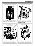
1. Fill the solution tank.
2. Attach one end of a solution hose to a wand or other tool, the other end
to the Speedster’s® front quick disconnect.
3. Attach one end of a vacuum hose to the tool, the other end to the
Speedster’s® Cuff-Lynx™ vacuum hose port.
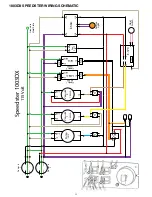
4. Plug in power cords.
• 1000DX-200 models
– Plug single cord into single, 20A grounded wall
outlet.
• 1001DX-200 models
– Using two separate circuits/breakers, plug the left
power cord into 20A grounded wall outlet to turn on Vac 2 and Heater 2.
Plug the right power cord into separate 20A grounded wall outlet to turn on
Vac 1, Heater 1 and Pump.
• 1003DX models
– Using two separate circuits/breakers, plug the left
power cord into 20A grounded wall outlet to turn on Vac 2 and Heater 2.
Plug the right power cord into separate 20A grounded wall outlet to turn on
Vac 1, Heater 1 and Pump.
• 1005DX models
– Using two separate circuits/breakers, plug the left
power cord into 20A grounded wall outlet to turn on Vac 2. Plug the right
power cord into separate 20A grounded wall outlet to turn on Vac 1 and
Pump.
The amber light indicator on the switch plate will illuminate brightly when
cords are plugged into two separate circuits. Do not use extension cords
longer than 50 feet.
5. Turn on switches.
• 1000DX-200, 1005DX models – Turn on Vac 1, Vac 2 and Pump
switches.
• 1001DX-200 and 1003DX – Turn on Vac 1, Vac 2 and Pump switches.
Turn on Heater switch if heat is being used. Wait several minutes for water
to heat. Heater switch has three positions: Off (middle); 1,000 watts using
one heater (left); and 2,000 watts using two heaters (right). Red lights on
panel display indicate watts selected: one light = 1,000 watts; two lights =
2,000 watts; no lights = heaters are off.
6. 1003DX and 1005DX models – Prime Valve and Pressure Regulator
are located on the lower front of the extractor. To prime the pump, turn the
valve to the Prime position for 30 seconds, then turn horizontally to the
Run position. Turn the Pressure Regulator to the left to decrease the water
pressure. Turn to the right to increase water pressure. Level will be visible
on the pressure gauge. Monitor while adjusting, using Pressure Gauge on
Switch Panel.
7. Begin cleaning. Make two dry passes to every wet pass. Work away
from cords to avoid damage. To clean heavily soiled areas, repeat clean-
ing from a different direction.
8. Use a foam control solution in the recovery tank to prevent motor dam-
age and check for foam build-up in recovery and solution tanks.
9. Empty the recovery tank as needed when the internal ball float auto-
matically shuts off the vacuum. Attach the 45˚ drain elbow to the drain
spout in back. Lift up the dump valve and empty tank.
10. To relieve water pressure from the solution hose before disconnecting
it, squeeze the tool’s trigger five seconds after turning the power switches
off.
11. Once machine is off, unplug power cords. Remove solution and
vacuum hoses. Empty the recovery tank by attaching the 45˚ drain elbow
to the drain spout in back. Lift up the dump valve and empty tank.
12. 1003DX and 1005DX models – Water remaining in the solution tank
can be emptied by turning the Prime Valve to the right to move water into
the recovery tank. Empty recovery tank.
Please note: Your pump features a pressure switch, to protect vital
components. A minimum spray jet size of 02 needed for use with this
pump. Using a jet size smaller than this can cause back-pressure to
the pump, leading to an over-heat condition. Make sure that your tool
has a jet size of 02 or larger prior to use.
After Use
1. Before storing machine, drain, rinse and dry tanks and vacuum hose of
water and solution.
2. Store in a dry are in the upright position.
3. Open recover tank cover to promote air circulation.
4. Store indoors in a dry area. If storing in freezing temperatures, make
sure the machine and solution system are completely drained and dry.
Maintenance Schedule
Latches are located in back to open tank for internal maintenance. To
keep machine in good working condition, follow machine’s daily and
weekly maintenance procedures. Check valves and relief valves should be
replaced annually.
Maintenance item
Daily
Once a week
Clean and inspect tanks.
Clean and inspect hoses.
Check and clean internal filters by twisting
off, rinsing with clean water and replacing.
Check power supply cable.
Clean machine with all-purpose cleaner
and cloth.
Check spray nozzles.
Flush solution system with Mytee
®
System
Maintainer.
Remove and float shut-off screen from
tank and clean. Simply pull off.
Inspect vacuum hoses for holes and loose
cuffs.
Inspect spray pattern for clogging. If
clogged, remove spray tips and soak them
in a recommended liquid neutralizer for
up to six hours. To remove spray tip, twist
spray tip body counter-clockwise.
Lubricate wheels with water resistant oil.
Inspect machine for water leaks and loose
hardware.
x
x
x
x
x
x
x
x
x
x
x
x
Trouble Shooting
There is no power.
1. Plug machine in proper outlet.
2. If using two cords, make sure each is plugged into a separate circuit.
3. Check circuit breaker. Reset circuit breaker, other items should not run
on the same circuit as the machine. Outlet must be a 20-amp circuit.
Pump does not work properly
1. Snap quick disconnects firmly together.
2. Check solution tank; may be empty.
3. Jets clogged, remove jet and flush clean.
4. Filters clogged, remove filters and rinse clean with water.
5. Heater is blocked; flush out with Mytee’s® System Maintainer.
6. If brass check valve is stuck, replace valve.
7. Check pump wire. May need to reconnect wire.
8. Switch plate may need to be replaced.
9. If pump motor brushes are worn, replace pump.
*
A minimum spray jet size of 02 needed for use with this pump.
1001DX-200 or 1003DX heater does not work properly
1. If sensor mounted on the heater has popped, reset sensor by pushing
in button.
2. Heating element may need to be replaced.
Vacuum motor does not work properly
1. Check that hose is tightly connected.
2. Close drain hose valve completely.
3. Secure the vacuum tank tightly.
GENERAL INFORMATION


