background image

Copyright © Parallax Inc. 

ELEV-8 Quadcopter Kit (#80000) 

Version 1.

1

   Page 16 of 26  


Step 8: Configure your Transmitter  


1.


For best results, follow the Transmitter Setting Recommendations in the table 
below to configure your Transmitter. 


2.


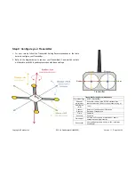
Refer to the diagram below to see how your Transmitter’s 2-axis joystick controls 

will translate into ELEV-8 quadcopter motion with these settings.   


Transmitter Setting Recommendations

Box Model Type 

ACRO (Plane Mode) 

End point 

adjustment 

Set to 50% initially. (If the ELEV-8 still seems too 
reactive, reduce to 30% until you get used to flying it.) 

Dual-Rates 

(D/R) 

100% 

Channel 
Reverse 

Normal: Hi Tech Spektrum, JR brands 
Reversed: Futaba brand 

Trims Centered 

Sub-trims Centered 

Gain Adjust 

Set Gain on 5

th

 channel.  Start with 25%, add or 

subtract based on flight stability 

Exponential 

After gaining experience, add up to 30% into aileron 
and elevator 

Transmitter 

Throttle 

Aileron 

Elevator 

Rudder 

Содержание ELEV-8

Страница 1: ...control software Custom plates protect motors and electronics Designed to easily attach a camera mount Specifications Weight without battery 2 5 lbs 1 13 kg fully assembled Payload capacity excluding...

Страница 2: ...adcopter could cause risk of catastrophic equipment failure personal injury to you or others and property damage Perform initial electronic speed controller ESC programming before installing the prope...

Страница 3: ...3 00025 4 Standoff 4 40 1 1 4 Nylon 800 00021 2 16 Red Pluggable Jumper Male 712 00004 4 Washer 6 3 8 OD Zinc 750 90002 4 Brushless 1000Kv Motor ELEV 8 Airframe Kit Contents 80050 710 00100 8 Screw 4...

Страница 4: ...ms Required RC radio controller and receiver 5 channel minimum required for flight LiPo Battery 3000 to 4400 mAh 3 cell 30 C discharge rate LiPo Battery Charger Tools Required Soldering iron solder an...

Страница 5: ...Copyright Parallax Inc ELEV 8 Quadcopter Kit 80000 Version 1 1 Page 5 of 26...

Страница 6: ...ollow the instructions below 1 Gather together your motors the red 16 AWG wire EC3 connectors wire cutters wire stripper ruler and soldering supplies 2 Using a ruler and wire cutters measure and cut t...

Страница 7: ...1 8 inch 0 3 cm of metal on the end of each speed controllers blue wire leads 7 Solder an opposite gender EC3 connector to the end of each speed controllers blue leads 8 Connect the male EC3 connector...

Страница 8: ...9 cm pieces 36 pieces total 2 Slip a piece of tubing over each solder joint on each motor lead 3 Apply heat with a heat gun or blow dryer to shrink the tubing over the solder joint as shown top 4 Slid...

Страница 9: ...Use two more 3 8 Panhead Screws and Internal Tooth Lock Washers item 6 to attach each Motor Mount top plate item 3 to the Nylon Standoffs item 7 4 One end of each Boom item 4 has two holes spaced abo...

Страница 10: ...Screw Pan head Stainless Steel 2 3 Motor Mount top 1 4 Boom Arm Black 1 5 3 8 Screw Pan head Stainless Steel 4 6 Internal Tooth Lock Washer 4 4 7 Nylon Standoff 4 40 x 5 8 2 8 Motor Mount Bottom 1 9 S...

Страница 11: ...s and two black white Booms 2 Locate the black and red 22 AWG wires in the ELEV 8 Electronics Kit Cut each 22 AWG wire into two pieces approximately 8 inches 20 cm long and then strip 1 4 inch 0 6 cm...

Страница 12: ...3 Position a Motor Boom assembly item 2 on the Bottom Chassis Plate item 3 The Boom tube rests on top of the plate with the motor axle pointing upward and the LED tape facing downward The free end of...

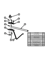
Страница 13: ...1 3 4 5 2 ITEM NO PART NUMBER QTY 1 Stand off Nylon 5 8 4 40 screw size 2 2 Assy Boom Arm 1 3 Quad Chassis 1 4 Screw 4 40 1 1 4 pandhead ss steel 1 5 Screw 4 40 1 1 4 panhead SS steel 1...

Страница 14: ...bing past each of the two solder joints you just made on the power harness so that they sit closest to the ESCs Don t shrink them yet just keep them out of the way of the solder joints 4 Position the...

Страница 15: ...it You will need two bullet connectors and one plastic housing 10 Solder a bullet connector onto the end of each 12 AWG lead Insert the exposed tip of the wire into the cup end of the bullet connector...

Страница 16: ...on with these settings Transmitter Setting Recommendations Box Model Type ACRO Plane Mode End point adjustment Set to 50 initially If the ELEV 8 still seems too reactive reduce to 30 until you get use...

Страница 17: ...to line up the black wire with the red wire with and the white wire with Signal WARNING Do not connect to the Programming Card s BEC port and Batt port at the same time this would damage the card 3 Se...

Страница 18: ...wo black checkered white LED Booms 3 Put a piece of tape on the output shaft of each motor so you can easily tell the direction of rotation 4 Connect an ESC s 3 pin socket to the Throttle port on your...

Страница 19: ...on Standoffs item 1 3 Attach each Nylon Standoff item 1 to the top of the Top Chassis Plate item 2 with a 3 8 Panhead Screw item 3 4 Attach the Top Chassis Plate to the standoffs on top the Booms usin...

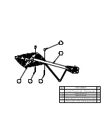
Страница 20: ...1 2 3 ITEM NO Description QTY 1 Stand off nylon 1 1 4 Thread 4 2 Quad Chassis 1 3 Screw 4 40 3 8 Pandhead stainless steel 4...

Страница 21: ...ITEM NO Description Part Number QTY 1 Screw 4 40 3 8 panhead stainless steel 710 00036 4 2 4 SS Steel Washer 4 3 Rubber Grommet 4 4 HoverFly Open PC Board 1 5 ELEV 8 Control Board Mount Plate Assy 72...

Страница 22: ...Control Board Top Plate over the Control Board The small hole near the center of the Control Board Top Plate is for a light pipe Make sure this hole is directly above the LED on the Control Board This...

Страница 23: ...omes 5 8 long Cut to length needed ITEM NO PART NUMBER QTY 1 light tube 1 2 Screw 4 40 x 1 Pandhead SS Steel 4 3 ELEV 8 Control Board Top Plate 1 4 Spacer Nylon 1 2 4 40 screw size 4 5 Assy PC Board H...

Страница 24: ...r on the front edge of the Control Board 1 Connect the Receiver to the Receiver Port with the five signal connections listed below Use the 3 wire extension cables included in the ELEV 8 Electronics Ki...

Страница 25: ...s are rounded side up 1 Disconnect the battery from the Power Harness 2 Refer to the diagram on this page for the correct placement of each blade 3 Connect each blade to its motor referring to the dia...

Страница 26: ...1 2 3 4 6 5 Use Blue Loctite Before installing ITEM NO PART NUMBER QTY 1 Propeller Nut 1 2 10 Inch Propeller 1 3 Cone Lock 1 4 Collet 1 5 Motor 2 1 6 Set Screw 2...

Отзывы: