


Mounting the QTIs
1.
Match the components in your kit to the Kit Contents listed above to make sure all pieces are
present. If anything is missing, contact Parallax Tech Support.
2.
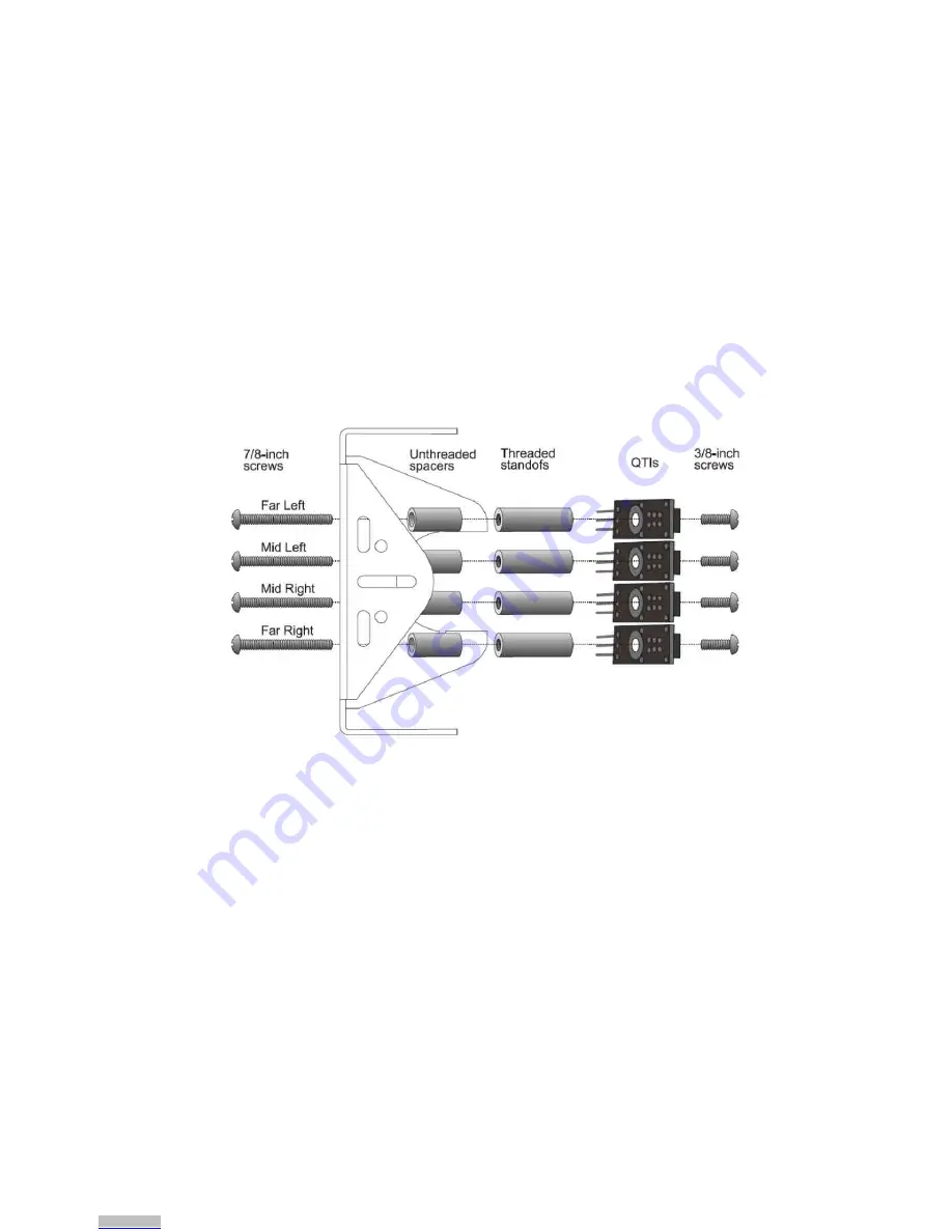
Referring to Figure 1, insert the 7/8-inch screws through the top of the small robot chassis, at
the three slots near the front. Two screws will go through the center slot, and one screw each in
the right and left slots.
3.
On the underside of the chassis, slip a 1/2-inch unthreaded spacer on each screw, followed by a
1-inch threaded standoff.
4.
Attach a QTI sensor to the other end of each threaded standoff, using a 3/8-inch screw. The
sensors should be facing downwards, and the 3-pin headers on each sensor should be pointing
towards the back of the chassis.
5.
If necessary, slightly loosen the 7/8-inch screws and adjust the position of the QTI sensors so
that they are closely positioned edge to edge.
6.
Tighten all connections securely.
.
Figure 1 – Mechanical Assembly
Building the Sensing Circuits
Each QTI B pin is tied to Vss (Ground/GND) and each W pin is connected to Vdd (5V). R pin connects to
an I/O pin:
•
Far right to P4
•
Mid right to P5
•
Mid left to P6
•
Mid right to P7
√
Use the schematic (Figure 2) and the wiring diagrams (Figure 3) on the next page to build the
circuits for the three-pin headers. Be sure to use the correct breadboard setup for your specific
robot (Boe-Bot, ActivityBot, or Arduino Shield-Bot). Although there are many ways this circuit can
be built, these setups are simple and thrifty with breadboard real-estate. If you are using a Boe-
Bot with a HomeWork Board (instead of a Board of Education), it won’t interfere with the servo
connections.
Copyright © Parallax Inc.
QTI LIne Follower AppKit (#28108)
v3.0 2/25/2015 Page 2 of 4
Downloaded from
Downloaded from


