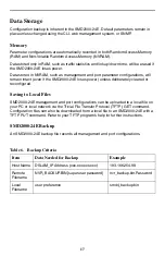
Paradyne SMD2000-24E Скачать руководство пользователя страница 19

19

Reset Button

The reset button is a small, unmarked button just to the right of the E1 uplink LEDs on 
the chassis faceplate. The button is recessed and you need a paper clip, mechanical 
pencil, or similar tool to press it.

System Reset

A system reset will clear all statistical data (stored in RAM) and restart the 
SMD2000-24E. It will not clear NVRAM; management settings and port configurations 
will remain unchanged. 

To perform a system reset, press the Reset Button for one second. The reset takes 
approximately one minute to complete.

System Clear

A system clear will erase both RAM and NVRAM and restart the SMD2000-24E, 
restoring all management and port configurations to their original default settings. To 
clear the system, press the Reset Button for one  second, release, and, within five [5] 
seconds, press the Reset Button again for one second. 

After the first pressing of the Reset Button, the passage of five seconds is indicated by 
the successive flashing of the SHDSL Link (LK) LEDs for Ports 1-5; if you do not press 
the Reset Button a second time within the allotted five seconds, the SMD2000-24E will 
perform a system reset (see 

System Reset

, above), rather than a system clear. The 

clear takes approximately one minute to complete.

C

AUTION

:

Clearing NVRAM to restore original default settings includes restoring the default IP 
Address, Subnet Mask and Gateway. Additionally, Inband Management will revert to 
its original default setting (OFF) and you will be required to establish a direct PC to 
SMD2000-24E connection for any subsequent configurations. Refer to the 

Reset Button

Содержание SMD2000-24E

Страница 1: ...k Interface Modules Optional 5 Tabletop Installation 7 Rack Installation 8 Powering Up the SMD2000 24E 9 Connecting the SHDSL RJ21 Cable 11 Connecting to the Remote SHDSL Modems 12 Verifying the Conne...

Страница 2: ...notice to Paradyne and an agreement in writing to additional terms 3 The Licensee shall not reverse engineer decompile or disassemble the Software in whole or in part 4 The Licensee shall not copy the...

Страница 3: ...not be assigned sublicensed or otherwise transferred by the Licensee to any third party without the prior written consent of Paradyne 8 This Agreement and the license granted under this Agreement shal...

Страница 4: ...ur sales representative Site Selection Criteria In choosing a location for the installation of this product Select a restricted access area where admittance is limited to trained and authorized servic...

Страница 5: ...uires an Ethernet uplink connection or if you require an additional E1 or T1 backhaul The SMD2000 24E supports the following 1 port UIMs only UIM E1 UIM T1 UIM 10 100 CAUTION Disconnect all power sour...

Страница 6: ...e lip of the SMD2000 24E faceplate at the selected port opening such that the UIM PCB is face down and the UIM label shows through the port opening with the UIM model name along the right edge 4 Align...

Страница 7: ...inal eight flathead screws as depicted in Step 1 on page 5 Tabletop Installation Procedure To install the SMD2000 24E on a table desk shelf or remote cabinet 1 Affix the four provided rubber pads to t...

Страница 8: ...e chassis onto the rack and secure the rack mount brackets to the sides of the rack using one of the two provided sets of four rack mount screws whichever size fits the rack being used 3 Check the rac...

Страница 9: ...r ground wire with the two holes on the small unpainted section on the left side of the back of the chassis Secure the terminal lug to the chassis with two 10 32 screws 2 Connect the other end of the...

Страница 10: ...he screw into the terminal block same terminal from which it was removed 5 Remove the right hand screw labeled from the same terminal block slide the ring terminal of your negative lead onto the shaft...

Страница 11: ...However if you wish to run subscriber lines at settings other than the SMD2000 24E defaults configure the subscriber lines prior to connection Parameter settings may be changed using the Command Line...

Страница 12: ...or 180 degree cable both the left and right sides of the RJ21 plug connector should be secured to the socket Connecting to the Remote SHDSL Modems A primary feature of the SMD2000 24E is its capabili...

Страница 13: ...nfigured prior to connection if you intend to run the group with parameter settings other than the defaults Single Line SHDSL Connection A single line SHDSL subscriber connection may be established wi...

Страница 14: ...equires only one uplink connection for operational purposes although a second E1 uplink connection may be desired for redundancy Additionally the two E1 uplink ports may be bonded together for a singl...

Страница 15: ...0 0 0 0 Protocol All Speed 272 kbps VLAN Priority 0 none VLAN Range 0 0 off Table 2 E1 Defaults Parameter Default Frame Type Cyclic Redundancy Check CRC Line Code High Density Bipolar 3 Zeros Substitu...

Страница 16: ...nagement VLAN ID 0 off TFTP Trivial File Transfer Protocol on Management IP Address Filter Range 0 0 0 0 255 255 255 255 all Uplink DSLAM Interconnection 1 neither off Table 4 Username and Password De...

Страница 17: ...loses power unless deliberately cleared or reconfigured Saving to Local Files SMD2000 24E management and port configurations can be uploaded to a local file on your PC or local network via the Trivial...

Страница 18: ...4 6 8 A dash indicated range nvr_portcfg bin Password 1 6 12 Or using the keyword all nvr_portcfg bin Password 1 all Table 7 Template Criteria Item Data Needed for Backup Example Host Name DSLAM_IP Ad...

Страница 19: ...l default settings To clear the system press the Reset Button for one second release and within five 5 seconds press the Reset Button again for one second After the first pressing of the Reset Button...

Страница 20: ...s constant rate Table 9 LEDs 1 of 3 State Indication Additional Information PWR power Solid green SMD2000 24E is receiving power Both power terminals are connected Solid amber SMD2000 24E is receiving...

Страница 21: ...pertain to remote network access of the SMD2000 24E LK E1 Uplink Port 1 and 2 Flashing green E1 uplink connection is established and active The uplink port has received valid data from the remote E1...

Страница 22: ...te E1 provider equipment has lost a connection with an intermediate device and is receiving an AIS or RAI SHDSL LK Ports 1 24 Flashing green SHDSL connection is established and active The port has rec...

Страница 23: ...or Pins Ring Tip Port 1 1 26 Port 13 13 38 Port 2 2 27 Port 14 14 39 Port 3 3 28 Port 15 15 40 Port 4 4 29 Port 16 16 41 Port 5 5 30 Port 17 17 42 Port 6 6 31 Port 18 18 43 Port 7 7 32 Port 19 19 44 P...

Страница 24: ...thernet RJ45 Connection Pin Connection 1 Rx 2 Rx 3 Tx 4 not used 5 not used 6 Tx 7 not used 8 not used Table 12 E1 RJ45 Pin Assignments Pin Function Pin 1 Rx Ring Pin 2 Rx Tip Pin 3 not used Pin 4 Tx...

Страница 25: ...Pins not shown are unused Table 13 DB9 to 8 Pin Modular Adapter Pinouts Pin 8 Pin Modular Port Direction PC RS232 Serial Port Pin 1 Transmit Data TxD RxD Receive Data 2 2 Data Set Ready DSR RTS Reque...

Страница 26: ...15 CSA C108 8 EN55022 EN55024 Safety UL 1950 CSA C22 2 No 950 EN60950 CE Marking Environment Operating Temperature 40 F to 149 F 40 C to 65 C Storage Temperature 40 F to 158 F 40 C to 70 C Humidity 5...

Страница 27: ...lass A digital apparatus complies with Canadian ICES 003 Cet appareil num rique de la classe A est conforme la norme NMB 003 du Canada CE Marking When the product is marked with the CE mark on the equ...

Страница 28: ...nstall telephone wiring during a lightning storm Never install telephone jacks in wet locations unless the jack is specifically designed for wet locations Never touch uninsulated telephone wires or te...

Отзывы: