


9
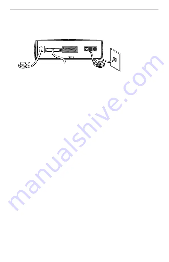
Connecting to the Network
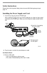
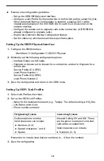
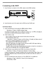
1. Insert the 8-pin connector on the RJ48S network cable into the NET interface.
POWER
COM
DBM
MDM
NET
99-16481
RJ48S
Jack
2. Insert the other end of the cable into the RJ48S modular jack.
3. Check that the Network DM (Data Mode) is on, and OOS (out of service) and
OOF/NS (out of frame/no signal) LEDs are off. If yes, the network interface is set
up correctly and is operational. If not, make sure both ends of the network cable
are properly seated and secured.
4. Verify that the network physical options are configured correctly.
Main Menu
→
Configuration
→
Network
→
Physical
5. Check Health and Status messages in the left column of the System and Test
Status screen to see the LMI status and verify that LMI is up.
Main Menu
→
Status
→
System and Test Status
If
LMI Down, Net1-FR1
appears for more than three minutes, or any other
network-related status message appears, refer to the status information in
Operation and Maintenance of the User’s Guide for possible reasons.
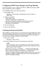
If the unit does not have ISDN backup capability, proceed to
Configuring SNMP Trap
Managers and Trap Dial-Out on page 13.
Setting Up the ISDN DBM
These instructions are for units with ISDN backup capability. The ISDN BRI DBM
supports up to 2 B-channels.
The following guidelines apply:
Central site configuration guidelines:
– Set up the ISDN DBM physical interface.
– Configure a Link Profile for each remote site.
– Configure the unit to answer calls from the remote sites.
– Leave Automatic Backup Configuration disabled.
– Manually create DLCIs for the configured ISDN Links.
– Manually specify ISDN DLCIs as alternate DLCIs for PVC Connections and
Management PVCs after the primary DLCIs have been automatically discovered
on the primary network link or have been manually configured.