Paradyne COMSPHERE 3910 Скачать руководство пользователя страница 2

2

Important Safety Instructions

1. Read and follow all warning notices and instructions marked on the product or included in this document.

2. This product is intended to be used with a three-wire grounding type plug — a plug which has a

grounding pin. This is a safety feature. Equipment grounding is vital to ensure safe operation. Do not
defeat the purpose of the grounding type plug by modifying the plug or using an adapter.

Prior to installation, use an outlet tester or a voltmeter to check the ac receptacle for the presence of earth
ground. If the receptacle is not properly grounded, the installation must not continue until a qualified
electrician has corrected the problem.

If a three-wire grounding type power source is not available, consult a qualified electrician to determine
another method of grounding the equipment.

3. Slots and openings in the cabinet are provided for ventilation. To ensure reliable operation of the product

and to protect it from overheating, these slots and openings must not be blocked or covered.

4. Do not allow anything to rest on the power cord and do not locate the product where persons will walk on

the power cord.

5. Do not attempt to service this product yourself, as opening or removing covers may expose you to

dangerous high voltage points or other risks. Refer all servicing to qualified service personnel.

6. General purpose cables are provided with this product. Special cables, which may be required by the

regulatory inspection authority for the installation site, are the responsibility of the customer.

7. When installed in the final configuration, the product must comply with the applicable Safety Standards

and regulatory requirements of the country in which it is installed. If necessary, consult with the
appropriate regulatory agencies and inspection authorities to ensure compliance.

8. A rare phenomenon can create a voltage potential between the earth grounds of two or more buildings. If

products installed in separate buildings are interconnected, the voltage potential may cause a hazardous
condition. Consult a qualified electrical consultant to determine whether or not this phenomenon exists
and, if necessary, implement corrective action prior to interconnecting the products.

9. In addition, if the equipment is to be used with telecommunications circuits, take the following

precautions:

Never install telephone wiring during a lightning storm.

Never install telephone jacks in wet locations unless the jack is specifically designed for wet
locations.

Never touch uninsulated telephone wires or terminals unless the telephone line has been disconnected
at the network interface.

Use caution when installing or modifying telephone lines.

Avoid using a telephone (other than a cordless type) during an electrical storm. There may be a remote
risk of electric shock from lightning.

Do not use the telephone to report a gas leak in the vicinity of the leak.

Содержание COMSPHERE 3910

Страница 1: ...o be used in conjunction with the COMSPHERE 3900 Series Modems Models 3910 and 3911 Point to Point Multipoint Installation and Operation Manual Document No 3910 A2 GN32 Warranty Sales and Service Info...

Страница 2: ...General purpose cables are provided with this product Special cables which may be required by the regulatory inspection authority for the installation site are the responsibility of the customer 7 Whe...

Страница 3: ...3 Notices...
Страница 4: ...ided to the telephone company 2 An FCC compliant telephone cord and modular plug is provided with this equipment This equipment is designed to be connected to the telephone network or premises wiring...

Страница 5: ...rporation commission for information Canada NOTICE TO THE USERS OF THE CANADIAN PUBLIC SWITCHED TELEPHONE NETWORK The Canadian Department of Communications label identifies certified equipment This ce...

Страница 6: ...ation on a loop may consist of any combination of devices subject only to the requirement that the total of the Load Numbers of all devices does not exceed 100 If your equipment is in need of repair r...

Страница 7: ...le NIM for modems installed in Slots 1 8 and one NIM for modems installed in Slots 9 16 required for dial line applications For installation of the COMSPHERE 3000 Series Carrier into a cabinet refer t...

Страница 8: ...or the DTE interface Connecting Model 3910 Modems with Supplied Cables Figure 1 shows how Model 3910 modems are connected to certain TELCO jack types using the appropriate cables 8 POSITION 8 CONDUCTO...

Страница 9: ...st Advance coordination with the telephone company is suggested when connecting the modem to telephone dial lines PSTN In the Permissive mode the modem s transmit output level is fixed at 9 dBm The te...

Страница 10: ...f the LCD Although a failure has occurred the modem will attempt to operate This allows you to activate a more thorough self test using the Test branch For a better understanding of the Test branch re...

Страница 11: ...ng configuration options to the Active Saved configuration area automatically saves them to the Active Operating configuration area The LCD displays Command Complete 7 The modem is now configured with...

Страница 12: ...o use AT commands after saving a factory configuration Other selections remove AT command control The only way to return to AT command control is through the DCP as described earlier in Using the DCP...

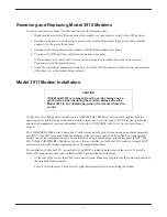
Страница 13: ...signed for installation in a COMSPHERE 3000 Series Carrier which supplies both the operating power and the leased and or dial network connections For correct power DTE dial line leased line and networ...

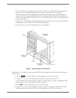
Страница 14: ...up self test in which all faceplate LEDs light Return to the rear of the carrier and tighten the rear connector plate Figure 2 Installing a Model 3911 Modem If the modem is to communicate with an ins...

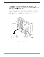
Страница 15: ...t 6 Once you have determined that the modem is installed properly and completed its power up self test rotate the circuit pack lock until it covers the faceplate latch Figure 3 and tighten the retenti...

Страница 16: ...y to power down the carrier to remove and replace a Model 3911 modem Perform the following steps 1 Rotate the circuit pack lock until the release tab is exposed 2 Press down on the release tab and pul...

Страница 17: ...x Frame Size RdcdAsyncBufSiz Test DTE RL CT140 DTE LL CT141 Test Timeout Rcv Remote Loop V54 Address V54 Device Type Misc StrapsWhenDisc Speaker Control Speaker Volume Access frm Remt RemAccssPasswrd...

Отзывы: