background image

1740 SHDSL 2/4-Wire Router User’s Guide 

1.2 LED 

Indicators 

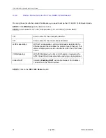
There are eight LEDs on the front panel of the router; the functions of the LEDs are described in the table 
below. 


Figure 1-1 Faceplate LED Indicators 


LED Color 

Mode 

Function 

On 

Power is supplied  

POWER Green 

Off Power 

is 

not 

supplied 

Off 

No data transmitted or received over the Ethernet link 

On 

The Ethernet link is established 

LAN 1–4  Green 

Flash 

Transmitting or receiving data over Ethernet link 

On 

The physical link through the RJ45 connection cable is 
established 

Flash 

The SHDSL line is training 

SHDSL 
LINK 

Green 

Off 

A SHDSL connection is not established 

On 

Receiving data over the SHDSL link 

SHDSL 
RX  

Green 

Off 

No data receiving over the SHDSL link 

On 

Transmitting data over the SHDSL link 

SHDSL 
TX 

Green 

Off 

No data transmitting over the SHDSL link 


8                                                                                      July 2004                                                                 1740-A2-GB20-00 

Содержание 1740 SHDSL

Страница 1: ...1740 SHDSL 2 4 Wire Router User s Guide Document Number 1740 A2 GB20 00 July 2004...

Страница 2: ...thods Internet Visit the Paradyne World Wide Web site at www paradyne com Be sure to register your warranty at www paradyne com warranty Telephone Call our automated system to receive current informat...

Страница 3: ...ration and applications of the 1740 SHDSL router Warning Before servicing or disassembling this equipment always disconnect all power and telephone lines from the wall outlet Use an appropriate power...

Страница 4: ...ce Configurtion 15 3 2 1 Bridge mode Service for one fixed IP address 16 3 2 2 Router Mode Service for Five Static IP Addresses 18 3 2 3 PPPoE 22 3 2 4 PPPoA 24 3 2 5 Password Setup 26 3 2 6 Setting t...

Страница 5: ...8 3 Multi NAT 46 8 4 Virtual Server 48 CHAPTER 9 DHCP 49 9 1 DHCP Server 49 9 2 DHCP Relay 50 CHAPTER 10 DNS PROXY 51 CHAPTER 11 IGMP 52 CHAPTER 12 VLAN 54 CHAPTER 13 MAINTENANCE AND DIAGNOSTICS 55 13...

Страница 6: ...User s Guide 16 1 4 Password Setup 70 16 1 5 Retrieve the Factory Default Settings 70 16 1 6 Disable the Web Browser 70 16 1 7 Save the Configurations 71 16 1 8 Login 71 APPENDIX A SPECIFICATIONS 73 6...

Страница 7: ...to be connected to the LAN The SHDSL router can be used for variety of applications including video conferencing remote training e commerce and other multimedia applications Easy configuration and mo...

Страница 8: ...eived over the Ethernet link On The Ethernet link is established LAN 1 4 Green Flash Transmitting or receiving data over Ethernet link On The physical link through the RJ45 connection cable is establi...

Страница 9: ...uter AC power adapter A power adapter is shipped with the router LAN connection cable To connect to the hub use a straight through RJ45 cable To connect to a PC use a crossover RJ45 cable Four wire 8P...

Страница 10: ...n the Ethernet connection is established the correspondent green LED on the front panel labeled LAN will illuminate steadily You can connect up to four PCs to the router Power connection Connect the s...

Страница 11: ...workstation to the same network segment as the router if for example the router is set to its default address of 192 168 1 1 we could set the PC to 192 168 1 133 and subnet mask 255 255 255 0 STEP 2 S...

Страница 12: ...0 SHDSL 2 4 Wire Router User s Guide STEP 5 After successfully logging in you will reach the main configuration page The left hand side has a menu and the right side is blank 12 July 2004 1740 A2 GB20...

Страница 13: ...ed The Basic menu bar sets up the device for quick setup The Advanced menu bar configures advance functions such as SNMP DHCP server and DNS proxy The menu also covers the maintenance function Main Wi...

Страница 14: ...on the Basic menu bar The Link Status screen has two tabs SHDSL Status and Performance SHDSL Status is used to monitor the SHDSL link and the Performance is used to monitor the SHDSL performance The f...

Страница 15: ...l RFC 1483 Bridged VC1 can work without any modifications VCs 2 to 16 are disabled If the VC is added on the Basic Wan Setup it will be added from VC2 to VC16 VC1 is already enabled for 0 33 If a PPPo...

Страница 16: ...CI Enter a value for the virtual channel identifier LLCEncapsulation With LLC encapsulation a link control header is added to the Ethernet packet that identifies the protocol type Ethernet This allows...

Страница 17: ...SL 2 4 Wire Router User s Guide To modify the VC click a VC from the Current ATM PVC List to display the parameters of the VC Change its parameters and click on the Modify button 1740 A2 GB20 00 July...

Страница 18: ...a value for the virtual channel identifier LLCEncapsulation With LLC encapsulation a link control header is added to the Ethernet packet that identifies the protocol type Ethernet This allows multiple...

Страница 19: ...e Add button The new VC is added in the Current ATM PVC List on the bottom screen To modify the VC click a VC from the Current ATM PVC List to display the parameters of the VC Change its parameters an...

Страница 20: ...u to use the new IP address and reboot the router immediately The Change button allows using the IP address immediately but you need to save the setting by clicking Save Reboot on the Basic menu bar T...

Страница 21: ...to type the IP address for the LAN port Click LAN Setup on the menu bar and type the IP address and Subnet should be 255 255 255 248 for static five IP address service and then click Apply Note After...

Страница 22: ...ed to the Ethernet packet that identifies the protocol type Ethernet This allows multiple protocols to be transmitted over the ATM Virtual Circuit VC Multiplexing With VC Multiplexing no link control...

Страница 23: ...is a networking operation that periodically default every 10 seconds checks the availability of a PPPoE PPPoA connection between the CO and CPE If the keep alive message is not acknowledged the connec...

Страница 24: ...llows multiple protocols to be transmitted over the ATM Virtual Circuit VC Multiplexing With VC Multiplexing no link control header is needed as the ATM Virtual Circuit is assumed to be carrying a sin...

Страница 25: ...SL 2 4 Wire Router User s Guide To modify the VC click a VC from the Current ATM PVC List to display the parameters of the VC Change its parameters and click on the Modify button 1740 A2 GB20 00 July...

Страница 26: ...y to complete the settings and save the setting by entering the Save Reboot screen on the basic menu bar Terminal Type When the router is connected to the DSLAM select CPE When the router is connect t...

Страница 27: ...static bridging and Spanning Tree Protocol STP functions 3 3 Spanning Tree Protocol The STP function is disabled by factory default To enable it click Enable in the Spanning Tree field and configure t...

Страница 28: ...s the MAC address of the PC Each PC has a unique MAC address such as 0a 01 1a 11 00 0b Port Map There are three modes to set up the data processing method for the LAN and ATM interfaces filter forward...

Страница 29: ...the flash memory To use these parameters after you restart the router you must save them to the flash memory To write the configurations click on the Save Reboot button Click on the Save button on th...

Страница 30: ...t your device to the factory defaults any changes to parameters will be lost and all parameters will revert to their default values To retrieve the factory default settings STEP 1 Click Erase Reboot o...

Страница 31: ...g screen STEP 3 You can click on the Change Reboot button to use the new IP address and reset the device immediately This does not require the Save action Alternatively you can click on the Change but...

Страница 32: ...er s Guide 4 2 Configuring the WAN Interface Click WAN Setup on the Basic menu bar and configure the VC to RFC 1483 Bridged RFC 1483 Routed PPPoE or PPPoA To set up these services refer to Section 3 2...

Страница 33: ...ak Cell Rate Sustainable Cell Rate and Burst Tolerance follow the steps below Click WAN Configure on the Advanced menu bar and click on the VCC tab on the main menu Select a VC in the Index field and...

Страница 34: ...can connect to an ISP To set up or configure the connection parameters to ISP click on WAN Configure on the Advanced menu bar Click on the ISP tab on the main screen Select an ISP and click on the Mo...

Страница 35: ...station The messages exchanged enable you to access and manage objects in an active or inactive stored MIB on a particular router 5 1 Enable SNMP To configure the SNMP parameters click on the SNMP bu...

Страница 36: ...s Guide 5 2 Disable SNMP Click SNMP on the Advanced menu bar and click on the Modify button at the bottom of the screen Choose Disable in the SNMP Service field and click on Apply to submit the setti...

Страница 37: ...ctions select Packet Filter from the advanced menu The screen will display as below showing a list of the currently configured filter entries 6 1 1 Add a Packet Filter entry To add a Packet Filter com...

Страница 38: ...lter Interface You can choose to apply this setting to a specific LAN or ATM interface This function is called Packet Binding Packet Binding is a function that can be used when we have multiple Virtua...

Страница 39: ...ter an RFC 1483 routed VC is created a static route as follows will be created Network ID Subnet Mask Next Hop IP 0 0 0 0 0 0 0 0 10 0 0 2 Click Routing Setup on the Basic menu bar to access the Routi...

Страница 40: ...sion 1 or Version 2 from the Version field STEP 4 Click Apply to submit the settings To configure the advance functions of the RIP click on the RIP tab on the main screen and configure the requested p...

Страница 41: ...ed the router will use the simple split horizon scheme to solve the problem Authentication Code Enter the password for authentication Mode Enabled Auto Summary Enabled Disabled The RIP function is now...

Страница 42: ...Table To display the routing table you can enter either of the following screens BASIC ROUTING SETUP ROUTING TABLE screen Advance Utilities Routing Table The following routing table appears after clic...

Страница 43: ...y private IP addresses are not transparent and assisting network administration The router supports many types of NAT functions including Fixed NAT this maps a private IP address to a public IP addres...

Страница 44: ...s 10 1 1 1 STEP 1 Click on NAPT on the Advanced menu bar STEP 2 Click on PAT and enter the following parameters Start Private IP Address Type the first IP address For example 192 168 1 140 End Private...

Страница 45: ...NAPT on the Advanced menu bar and click on the NAT PAT tab to access the NAT PAT Configuration screen Follow the steps below STEP 1 Select Fixed NAT STEP 2 Type the private IP address in the Private I...

Страница 46: ...es than private IP addresses One to one mapping When the number of private IP addresses is less than or equal to the number of public IP addresses each private IP address can be mapped to a public IP...

Страница 47: ...ivate IP Address For example 192 168 1 3 192 168 1 22 Start Global IP Address End Global IP Address For example 10 1 1 3 10 1 1 10 STEP 1 Fill out the above parameters in the relevant fields Start Pri...

Страница 48: ...ar to access the NAPT Configuration screen Global Port The virtual server provides service for the Internet users via this port Protocol TCP or UDP default TCP Private Address This is the IP address o...

Страница 49: ...location by the DHCP relay to obtain an available IP address 9 1 DHCP Server When a workstation is configured for automatic IP address assignment it broadcasts a request to the LAN When the router is...

Страница 50: ...n screen click on the BOOTP DHCP Relay tab and configure the following parameters BOOTP DHCP Relay Enable IP Address This defines the IP address of the remote DHCP server After completing the settings...

Страница 51: ...tables and when one is not found it forwards the request to a remote server Click DNS Proxy on the Advance men bar and configure the following parameters DNS proxy Enabled Disabled factory default di...

Страница 52: ...group memberships to any immediately neighboring multicast routers STEP 1 Add a VC and set it to RFC 1483 Routed mode STEP 2 Click IGMP Proxy on the Advanced menu bar STEP 3 Click Enable and choose th...

Страница 53: ...1740 SHDSL 2 4 Wire Router User s Guide STEP 4 Click Apply to submit the settings 1740 A2 GB20 00 July 2004 53...

Страница 54: ...s will be transmitted or received from these ports to the appointed PVC The packets of the VLAN groups are not routable Packets that do not belong to the VLAN group are routable Parameters and buttons...

Страница 55: ...ns This section describes how to achieve these tasks using the console port or LAN port In the above diagram the TFTP server is a PC with TFTP software installed If you will use the console port to pe...

Страница 56: ...n to the right Homepage upgrade Check Download and choose Homepage in the column to the right Configuration backup Check Upload and choose Configuration in the column to the right Retrieving Configura...

Страница 57: ...Guide The following is an example of how to set up the parameters for homepage upgrade To upload the configurations check Upload select Configuration and click on the Apply button to submit the setti...

Страница 58: ...Flow Type Choose the F5 loopback type Seg is the segment loopback It verifies the connection between the router and DSLAM Ete is the end to end loopback verifying the connection between the router and...

Страница 59: ...eturn message This diagnostic function can verify if the remote host is reachable Ping can also measure the round trip time to the remote host Click Utilities on the Advanced menu bar and click on the...

Страница 60: ...e Router User s Guide 13 4 Performance Monitoring System statistics Click System Statistics on the Advanced menu bar to monitor the interface status and collect the statistics of the TCP IP 60 July 20...

Страница 61: ...n In Octets The number of Octets bytes received InUncastPkts The number of unicast packets received InUncastPkts The number of broadcast packets received InDiscards The number of packets received that...

Страница 62: ...n the TCP IP tab at the top of the System Statistics page The TCP IP page displays the IP statistics UDP statistics TCP statistics and ICMP statistics Interface Click Interface Monitor on the Advanced...

Страница 63: ...monstrates a school application as an example Location A 10 164 32 9 Netmask 255 255 255 252 Location B 10 164 32 10 Netmask 255 255 255 252 Network of the School 210 240 117 0 Netmask 255 255 255 128...

Страница 64: ...de Enter the parameters of the static route and click on the Add button Click LAN Setup on the Basic men bar After typing LAN IP 10 164 32 10 and Netmask 255 255 255 252 click on Apply to submit the s...

Страница 65: ...Definition 1 NC 6 NC 2 TD 7 NC 3 RD 8 NC 4 NC 9 NC 5 GND LAN Port RJ45 Pin number Definition Pin number Definition 1 RD 5 NC 2 RD 6 TD 3 TD 7 NC 4 NC 8 NC LINE Port RJ45 Pin number Definition Pin numb...

Страница 66: ...uter 16 1 1 Login For access by console the console PC should be installed with a standard VT100 emulation program such as HyperTerminal 5 or Telix You must connect the router to a PC using a serial c...

Страница 67: ...Ctrl L keys simultaneously to return to the Home Menu T Hold down the Ctrl T keys simultaneously to reset the value or statistics counted R Hold down the Ctrl R keys simultaneously to refresh or resto...

Страница 68: ...he cursor in the menu you can enter the requested screen by entering the number For example to enter MAIN ADVANCE DHCP RELAY follow the steps below STEP 1 Press the 2 key to enter the Advance menu and...

Страница 69: ...3 Press the 2 key and then press the Enter key in MAIN ADVANCE DHCP STEP 4 Now you have reached MAIN ADVANCE DHCP RELAY 16 1 3 Motoring the SHDSL Line Status Enter MAIN BASIC SHDSL to monitor the SHD...

Страница 70: ...r the user password in the New User Password and confirm the password by retyping the password in the Retype Password field 16 1 5 Retrieve the Factory Default Settings Enter BASIC DEFAULT and press t...

Страница 71: ...o the flash memory To write the configurations enter MAIN WRITE and press the Y key After saving the configurations you will be prompted if you need to reboot the device Press the Y key to reboot the...

Страница 72: ...click OK 192 168 1 1 is the default IP address If it was changed use the new IP address to login STEP 3 Enter the user name and password and press Enter to login The default password and user name are...

Страница 73: ...ver AAL5 Route RFC 2684 1483 PPP over Ethernet RFC 2516 PPP over AAL5 RFC 2364 ATM Attributes VCs 16 AAL type AAL5 ATM service class UBR CBR VBR ATM UNI support UNI3 1 4 0 OAM F4 F5 Management Console...

Страница 74: ...DHCP BOOTP Yes PAP CHAP Yes Automatic IP and DNS Assignment RFC 1877 Power Supply External power adapter 110 VAC or 230 VAC Frequency 50 60 Hz Environmental Conditions Operating temperature 0 50 degr...

Отзывы: