


Chapter 4: Connection
15
Connecting Power
The IPR512 Receiver is powered at 100-240 VAC (50-60 Hz) and is compatible with multiple
types of electrical outlets. If you require a different type of power cable, contact your local
Paradox dealer for more information. For information on technical specifications refer to
“IPR512 Receiver Technical Specifications” on page 7.
To Connect the Power Cable
1. Connect one end of the AC Power cable to the AC Power connector on the IPR512
Receiver.
2. Connect the other end of the power cable to the electrical outlet or UPS source.
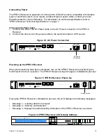
Figure 12: AC Power Connection
Powering up the IPR512 Receiver
When all connections have been completed, turn on the IPR512 Receiver by positioning the
On/Off switch to the On position. The IPR512 Receiver will go through an initialization process.
Figure 13: IPR512 Receiver Power-Up
During the IPR512 Receiver’s initialization process, the LCD displays the following messages:
•
Message 1 - “Loading data from receiver”.
•
Message 2 - “Memory card detected”.
•
Message 3 - Displays the default setting information of the IPR512 Receiver, as shown.
Figure 14: IPR512 Receiver LCD Display Settings
COM
1
(PC)
COM
2
(SERIAL OUT)
LAN
WAN
1
WAN
2
INPUT
TRIGGER
C
1 COM NO
OUTPUT
RELAY
I
O
P A R A D O X . C O M
AC Power
Connection
COM
1
(PC)
COM
2
(SERIAL OUT)
LAN
WAN
1
WAN
2
INPUT
TRIGGER
C
1 COM NO
OUTPUT
RELAY
I
O
P A R A D O X . C O M
Power Switch
IP Monitoring Receiver
IPR512
Содержание IPR512
Страница 1: ...IPR512 GPRS IP Monitoring Receiver V1 2 Operations Manual...
Страница 63: ......


