


4
PARTS LIST
PART #
6608708
6608508
6274402
6275302
6609002
6610402
6546302
6609308
3116101
3116201
6610501
6576201
6176201
6542402
3103102
3102933
3102922
3102904
KEY
1
2
3
4
5
6
7
8
9
10
11
12
13
14
15
16
17
18
QTY
1
1
1
1
1
1
1
1
1
5
1
1
2
2
4
2
5
2
PART #
3102915
3102501
3102802
6480301
3102953
3102910
3102502
3102801
6692601
3119301
6236701
3116001
6140701
6177001
3103801
3108102
6075906
DESCRIPTION
3/8 X 3-1/4” BOLT
3/8” WASHER
3/8” LOCK NUT
3/8” FLANGE SPACER
1/2 X 2-3/4” BOLT
1/2 X 3” BOLT
1/2” WASHER
1/2” LOCK NUT
3 X 2” END CAP
2-1/2” ROUND END CAP
1-3/4” SQ. END CAP
1-1/4” SQ. RUBBER BUMPER
1 X 1” GLIDE
NON-SKID STRIP
5/16” SNAP LINK
1/4” QUICK DISCONNECT LINK
12 LINK CHAIN
QTY
2
10
11
8
1
3
4
2
1
2
1
1
8
2
3
1
1
DESCRIPTION
UPRIGHT
TOP BOOM
LOW ROW BAR
LAT BAR
LOW ROW ATTACHMENT
KNEE SUPPORT
CARRIAGE
LOW PULLEY HOUSING
4-1/2” PULLEY
3-1/2” PULLEY
LAT CABLE
LOW ROW CABLE
ROLLER PAD
1-3/4” X 5-1/4” PLATE
1 X 8” GRIP
3/8 X 2” BOLT
3/8 X 2-3/4” BOLT
3/8 X 3” BOLT
KEY
19
20
21
22
23
24
25
26
27
28
29
30
31
32
33
34
35
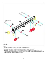
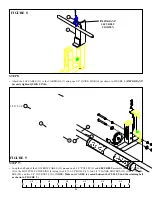
FIGURE 1
STEP 1:
• Insert two 2-1/2” ROUND END CAPS (28) to the LOW ROW ATTACHMENT (5) as shown in FIGURE 1.
• Attach two NON-SKID STRIPS (32) to the LOW ROW ATTACHMENT (5) as shown in FIGURE 1.
5
32
28


