


Thank you for purchasing the Parabody 848101 LAT OPTION. If unsure of proper use of equipment, call
your local Parabody distributor or call the Parabody customer service department at (800) 328-9714.
BENCH
2
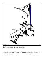
STEP 13:
FIGURE 13
• Insert the UPRIGHT (2) of the 848101 into the bench as shown in FIGURE 13.
14


