


- 13 -
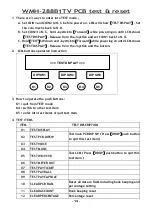
WMH-288B1TV PCB test & reset
1.
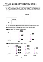
There are 3 ways to enter into TEST mode
:
:
:
:
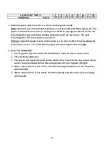
A. Set COIN1 and COIN2 to N.C. before power on. LCM will show
【
【
【
【
TEST DISPLAY
】
】
】
】
. Set
the coin mechs back to N.O.
B. Set COIN1 to N.C., hold Joystick to
【
【
【
【
Forward
】
】
】
】
while powering on until LCM shows
【
【
【
【
TEST DISPLAY
】
】
】
】
. Release from the Joystick and set COIN1 back to N.O.
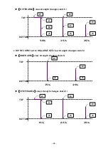
C. Hold
【
【
【
【
TEST
】
】
】
】
SW down and Joystick to
【
【
【
【
Forward
】
】
】
】
while powering on until LCM shows
【
【
【
【
TEST DISPLAY
】
】
】
】
. Release from the Joystick and the button.
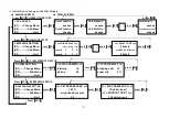
2.
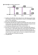
LCM buttons operation instruction
3.
How to operate the push buttons:
K1
:
:
:
:
quit from TEST mode
K4
:
:
:
:
switch to other test item
K5
:
:
:
:
enter into test items or quit test item
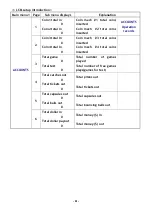
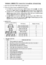
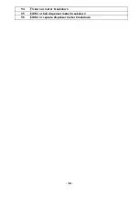
4.
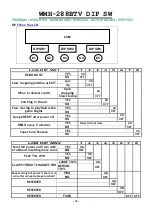
TEST ITEMS
ITEM
TEST DESCRIPTION
01
TEST DISPLAY
02
TEST PCB DIPSW
Test main PCB DIP SW
(
(
(
(
Press
【
【
【
【
DROP
】
】
】
】
push button
to quit this test item
)
)
)
)
03
TEST VOICE
04
TEST MUSIC
05
TEST W041158
Test LCM
(
(
(
(
Press
【
【
【
【
DROP
】
】
】
】
push button to quit this
test item
)
)
)
)
06
TEST METER OUT
07
TEST PAY TICKET
08
TEST PAY BALL
09
TEST PAY CAPSULE
10
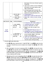
CLEAR PCB RAM
Reset all data in RAM including book keeping and
percentage setting
11
CLEAR ACCOUNT
Book keeping reset
12
CLEAR PERCENTAGE
Percentage reset
=== TEST DISPLAY ===
DIP SW1
DIP SW2
DIP SW3
K1
K2
K3
K4
K5