Instructions for use U2-light
Instructions for use U2 light
5
6
5) Tension of the back upholstery.
The back upholstery can be tightened or loosened by adjusting the Velcro band at
the back. The back upholstery also has a fl ap fastened with Velcro under the seat
upholstery. This can be moved back or forwards to obtain the required tension in
the lower section of the back upholstery (known as the seat bucket). By adjusting
these things you can form the lower part of the back upholstery to suit the shape
of your back and obtain good support for your lower back. Start by loosening the
band and sit as far back in the chair as you can. Then tighten the band to give you
good support. If it feels as though you are not sitting far back enough in the chair it
may be because the back upholstery fl ap is fastened too far forward under the seat.
Relax this fl ap and move it back.
Figure 9.
Balancing
3
4
6) Balancing the wheelchair.
The U2 Light has a fi xed back axle so balancing is achieved by moving the body
position in relation to the back axle. This can be done by moving the backrest
which can be fi xed in 3 different positions. The further back you place the backrest,
the more ‘rear balanced’ the chair will be. This means that the chair is light at the
front and you have more weight over the rear wheels. The chair is easier to drive
and it is also easier to tip up onto the rear wheels to negotiate kerbs and steps.
The chair should not be balanced too far back, however, because of the danger of
tipping backwards.
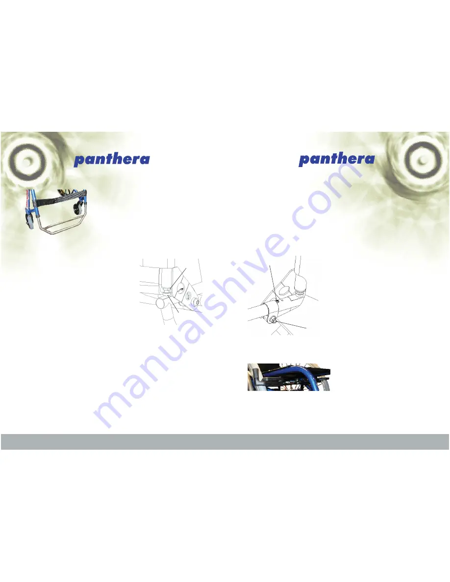
The backrest can be adjusted as follows, see
fi gure 9:
Unscrew the stop screws (3).
Loosen the bolt through the clamp and
the back attachment (4).
Knock the clamp back or forwards (back
if you want a more lightly balanced
chair, forwards if you prefer a more
heavily balanced chair).
Replace the stop screws in one of the
three alternative holes in the back frame.
Knock the clamp so that the back of the
clamp touches the stop screw.
Tighten the bolt (4) through the clamp.
1.
2.
3.
4.
5.
6.
Figure 10.
Single hand brake
Single hand brakes
This brake is situated underneath the seat
frame, see fi gure 10.
The brake can be locked by pulling it
forward at an angle and then pushing it
back.
Figure 8.
Adjusting the angle of
the backrest
2
4) Angle of the backrest.
Adjust the angle of the backrest by fi rst loosening
the lock nuts (1), see fi gure 8, using cap key no. 13,
and then screw the adjustment screws in or out (2)
using the 5mm socket head key. If you unscrew the
adjustment screws the backrest will tilt forward.
If you tighten the adjustment screws the backrest
will tilt backwards. It is important to adjust both
sides equally to avoid the backrest tubing becoming
crooked. Test this by putting the backrest in upright
position and checking that both adjustment screws
are touching the frame. Try out suitable backrest
angles and tighten the lock nuts once you are
satisfi ed.
1
Figure 7.
The calf band
3) Tension of the calf band.
The tension of the calf band can be adjusted
and will affect how far forward you place
your feet on the footrest. The appropriate
tension depends largely on how long or short
your legs are, as shown in fi gure 7.


