background image


BA_PH_UT300_EN_18-21.docx


16


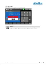
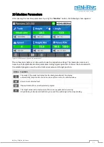
Height Abs


Setting of the absolute height in the range from 0 to 125: 


Figure 13: Absolute height 

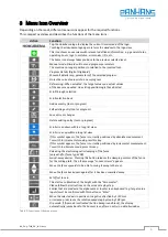
Action 

Function 


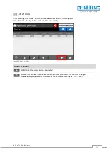
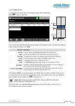
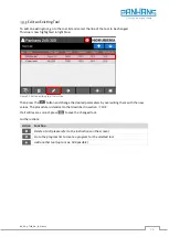
Confirmation of input + positioning enable 

 The positioning button 

 flashes 


Содержание Ultimo-Touch 300

Страница 1: ...Four Axis Touchscreen Control for Swivel Milling Machines Usable for the machine types 245 100 245 200 and 245 300 Operating instructions for the user level machine operator Four axis touchscreen con...

Страница 2: ...5 100 and 245 200 11 Fence 311 Machine Type 245 100 and 245 200 11 Fence 320 Machine Type 245 300 11 Additional Position Indicator with Fence 302 11 7 4 1 Button functions of the additional indicator...

Страница 3: ...al 15 Figure 13 Absolute height 16 Figure 14 Swivel angle for the milling spindle 17 Figure 15 Absolute fence 18 Figure 16 Incremental fence 19 Figure 17 Swivel away device dialog example type 320 20...

Страница 4: ...ate 001 AG Original version translated document created 2018 11 21 002 AG section 6 3 Stop System 301 and chapter 10 handwheel added 2019 03 31 003 AG New fence types chapter for additional indicator...

Страница 5: ...t Releasing the HSK quick changing system option Cutter rotation left Rotation direction left for the milling cutter changeover only at standstill possible Cutter rotation right Rotation direction rig...

Страница 6: ...ool or program Scroll screen down within a long list view Scroll screen up within a long list view If this symbol appears the fence is currently positioned by absolute measurement To switch to increme...

Страница 7: ...s Button Function Training The official machine instructions of the employers liability insurance association with all safety relevant information and instructions can be viewed here Machine To work w...

Страница 8: ...key Once the appropriate RFID key has been inserted into the RFID reader the user name appears in the upper left corner of the operator surface see Figure 3 Figure 3 Machine access username To access...

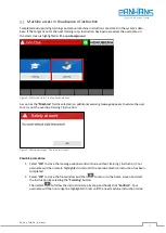
Страница 9: ...appears to advise the user to carry out the overdue training instruction Figure 5 Warning message Overdue Instruction Possible procedures 1 Select OK to close the message window and continue without...

Страница 10: ...al value and target value differ from each other or if the target position setpoint has not been reached As soon as the position Set has been reached and the two values for actual and tar get value ar...

Страница 11: ...le to read the position values not only at the control but also directly at the total fence 7 4 1 Button functions of the additional indicator When the key is pressed the incremental measurement funct...

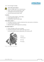
Страница 12: ...lacement battery unit 3 Prepare Phillips screwdriver e g PH 0x60 Disassembly see Figure 7 1 The battery compartment is located on the left side of the unit connections at the bottom 2 Unscrew the thre...

Страница 13: ...chine access control the master key must be inserted to enable the setup menu Figure 8 Main screen with Setup menu This menu is password protected and intended only for the administrator Therefore the...

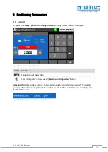
Страница 14: ...milling cutter Action Function Confirmation of the setting Start milling cutter at new speed Switch on milling cutter button Remark When the spindle is rotating the speed can only be corrected downwar...

Страница 15: ...es Further actions Action Function With this Reset Icon the axis can be set to 0 Perform calibration with the Zeromaster reference measurement adjusting unit see section 9 2 1 below 9 2 1 Zeromaster W...

Страница 16: ...UT300_EN_18 21 docx 16 Height Abs Setting of the absolute height in the range from 0 to 125 Figure 13 Absolute height Action Function Confirmation of input positioning enable The positioning button fl...

Страница 17: ...the swivel angle for the milling spindle is made in this mask The possible swivel range of the milling spindle is 45 5 Figure 14 Swivel angle for the milling spindle Action Function Confirmation of in...

Страница 18: ...on in mm In addition the compensation dimension for the partial fence can be set here Figure 15 Absolute fence Action Function Confirmation of input positioning enable The positioning button flashes S...

Страница 19: ...mask is used to enter an incremental fence position in mm Figure 16 Incremental fence Action Function Confirmation of input positioning enable The positioning button flashes Switch to absolute mode Fe...

Страница 20: ...late only for fence type 320 Then the note Loosen screws appears for fence type 320 or Remove clamping levers for types 302 and 311 both clamping levers must be completely removed to enable swivelling...

Страница 21: ...regular operation It shows the tool used with the selected program as well as all current actual values and target positions Action Function Flip mode If flip mode is activated button background blac...

Страница 22: ...appears Note If no tools have yet been created this list is empty Figure 19 Tool overview Action Function With this button a new tool can be created Manual mode Discards all loaded tool and program pa...

Страница 23: ...of the cutter is entered here in mm Spindle Mo This value is used in spindle assembly to compensate for the non cutting area e g for a spacer ring Enter the ring height in mm Correction Value Height...

Страница 24: ...ct line Then press the button and change the desired parameters by overwriting them with the new values The procedure is identical to that described in section 10 2 If all entries are correct press to...

Страница 25: ...nt of the tool Datum can be set individually To create a program for a tool first select the relevant line in the tool list by tapping it The active line is then highlighted in light blue Figure 22 Se...

Страница 26: ...he partial fence If all entries were made these must be confirmed with Enter Then use the select field Datum to define either the upper edge the tool center or the lower edge as reference point By usi...

Страница 27: ...ine mark the corresponding program line by touching it so that it is highlighted in light blue Then press to accept the program Further actions Action Function Add further program up to max 100 per to...

Страница 28: ...nce RS485 2 wire Figure 27 DIP switch settings 11 1 2 IP Settings Set the Service PC as follows IP Address 192 168 115 23 Subnet 255 255 255 0 Gateway 192 168 115 1 Start the WuTility software Figure...

Страница 29: ...right mouse button on the corresponding Com Server and select the menu item Set Network Parameters Figure 29 Open network parameters Enter the following values Figure 30 Set network parameters Press N...

Страница 30: ...ase scan the devices again Figure 32 Perform a new scan Double click on the selected line to access the WuT Com Server Web interface In the factory settings of the Com Server no password is assigned f...

Страница 31: ...he menu item SETUP Port 0 Serial to reach the parameter level of the serial inter face In the following menu click on UART Setup to configure the serial interface The following parameters must be set...

Страница 32: ...ck Back to leave the parameter level In the following menu click on Logout Figure 39 Com server logout You are now in the logoff area Here you have the possibility to save the configuration you just c...

Отзывы: