


BA_PH_245-100-300_EN_06-22.docx
38
14.2
Functions and Adjustment of the Milling Fences
Depending on the machine type and equipment, different fence types are used or can be retrofitted optionally:
•
Fence type 301 (standard for machine versions 245|100 and 245|200)
Total fence / partial fence manually adjustable (handwheel / adjusting screw).
•
Fence type 302 (option for machine versions 245|100 and 245|200)
Total fence and partial fence manually adjustable (two separate handwheels).
•
Fence type 311 (option for machine versions 245|100 and 245|200)
Total fence automatically and partial fence manually adjustable (adjusting screw).
•
Fence type 320 (standard for machine version 245|300, option for 245|100 and 200)
Total fence and partial fence automatically adjustable.
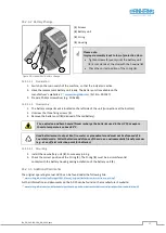
Increased risk of accidents and collisions! The adjustment and setting processes
described below may only be carried out when the milling cutter is stationary!
When milling with manual feed, a tool cover must always be used!
Remove chips and dust from the table top before adjusting the milling fence.
For maintenance of your fence, please refer to section
14.2.1
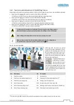
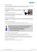
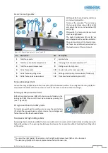
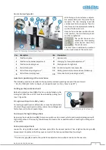
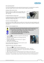
Fence Type 301
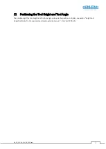
Figure 28: Operating elements Fence Type 301
With type 301, the total and partial
fence are manually adjustable. For ad-
justment, the clamping levers (
3
) and
(
6
) are released and the fence is ad-
justed via the hand wheel (
2
). After-
wards the two clamping levers (
3
) and
(
6
) must be re-tightened.
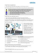
The partial fence can be
adjusted by the adjust-
ing screw (
5
) and read
off on the vernier scale.
The digital handwheel (
2
) of the total
fence is equipped with a position indi-
cator. This position is also visualised on
the touchscreen unit.
Pos. Description
Pos. Description
1
Total fence plate
7
Splinter tabs
2
Total fence handwheel adjustment
8
Clamping for fence plate adjustment
10
3
Total fence clamping lever
9
Sliding covers for high tools
4
Partial fence plate
10
Knurled screws for tool covers (
9
)
5
Partial fence adjusting screw
11
Milling protection & pressure device (folded up)
6
Partial fence clamping lever
12
Protective hood (unlocking rear left)
10
The two star grips (
8
) as well as the partial fence adjustment screw (
5
) are located on the rear side.
2
5
1
4
3
6
8
7
11
10
9
12