Panduit smartzone G5 Скачать руководство пользователя страница 11


SMARTZONE G5 INSTALLATION MANUAL 


10 


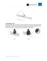
Power Cord Retention 
 

Integrated Cord Retention 

Each IEC C13 and C19 outlet on the PDU comes equipped with an integrated cord 
retention feature. This will allow you to secure the cord to the outlet without a cord 
retention bracket. 

1.   Plug in the power cord. 


2.  Using the tie wraps provided, slide the end of the tie wrap into the notch on the 

PDU next to the desired outlet and wrap around the cord.  


3.  Secure the tie wrap. 

Содержание smartzone G5

Страница 1: ...G5 PDU Installation Guide...

Страница 2: ...egrated Cord Retention 10 Locking Power Cord 11 Section 2 Installing the PDU 12 Vertical PDUs 12 Install Mounting Hardware 12 Vertical 0U PDU Single Installation 13 Vertical 0U PDU Two or More Install...

Страница 3: ...SMARTZONE G5 INSTALLATION MANUAL 2 Connecting the PDU to a Power Source 19...

Страница 4: ...DU must be reduced by a factor of 0 8 WARNING A risk of personal injury from electric shock and hazardous energy levels exists The installation of options and routine maintenance and service of this p...

Страница 5: ...hock install this PDU in a temperature and humidity controlled indoor environment free of conductive contaminants Do not operate near water or excessive humidity 90 maximum noncondensing Ambient tempe...

Страница 6: ...SMARTZONE G5 INSTALLATION MANUAL 5 Required Tools The following tools are required for installation Phillips screwdriver Torx screwdriver...

Страница 7: ...form factor with several mounting configurations available Panduit Monitored PDU Provides aggregate power monitoring to quickly identify potential power issues and reclaim available or under utilized...

Страница 8: ...al in a U space or in the True 0U space between the RETMA rails Hot Swappable Network Management Module allows power distribution during module replacement eliminating downtime 1Gb Ethernet eliminates...

Страница 9: ...1U PDUs can be installed in a U position in the rack or in the true 0U space on the side of the rack between the RETMA rails 2U 2U PDUs can be installed in a U position in the rack Load Segment and Ph...

Страница 10: ...se PDU Example There is one exception to the different colored receptacles per load segment The three phase half height high density model has two different load segments on each phase as shown in the...

Страница 11: ...es equipped with an integrated cord retention feature This will allow you to secure the cord to the outlet without a cord retention bracket 1 Plug in the power cord 2 Using the tie wraps provided slid...

Страница 12: ...Power Cord Optional locking power cords can be used on each IEC C13 Image A and C19 Image B outlet on the PDUs Several lengths are available to support any configuration The image below shows the lock...

Страница 13: ...When installing the mounting buttons use either mounting holes as a set Mounting button installation outlets facing the center of the rack 1 Align and install the mounting buttons with the screw hole...

Страница 14: ...re true for all vertical models except for the high density models Those units can only mount on its side with outlets facing the back of the rack Reference the high density PDU installation section f...

Страница 15: ...ight PDUs with outlets facing in towards center of the rack C Four half height PDUs with outlets facing in towards center of the rack High Density PDU Installation This unique form factor comes in bot...

Страница 16: ...AL 15 A B NOTE One full height can be installed per side of rack whereas two half height models per side one on the top and the other on the bottom 1U PDUs Mounting Options This unit can be installed...

Страница 17: ...unting Hardware Installation 1U PDU mounting in a U position of the rack 1 Install the cage nuts at the desired U location 2 Screw the mounting bracket ears into the RETMA rail surface at the U locati...

Страница 18: ...NE G5 INSTALLATION MANUAL 17 2U PDUs Mounting Options This unit can be installed in any U locations of the rack Mounting Hardware Installation 1 Install cage nuts at the desired U locations 2 Install...

Страница 19: ...ounding or bonding of ungrounded metal parts This bonding point can also be used to bond the PDU to a known earthed reference terminal in the building Per international regulatory requirements the pri...

Страница 20: ...enough length in the PDU power cord to reach the PDU power source 1 Turn the feed circuit breaker Off 2 Make sure that all circuit breakers on the PDU are set to On 3 Connect each PDU to an appropriat...

Отзывы: