


INSTALLATION INSTRUCTIONS CM501A
For Technical Support: www.panduit.com/resources/install_maintain.asp
Page 4 of 6
6.1
Hanger wire should be used to hang the enclosure
within a suspended ceiling.
Important:
Verify hanger
wire meets local building code. It is recommended to
use N0. 18 AWG solid steel wire as a minimum or any
comparable/equivalent wire or hanger system as
allowed by the applicable local code. Weight of the
enclosure, mounting brackets, and equipment does not
exceed 20 lbs. The enclosure is rated to hold up to
10 lbs of equipment.
6.2
Observe how the hanger wire used to hold the ceiling
support grid is secured to the building structure.
6.3
Remove one tile adjacent to the tile the enclosure will
be mounted in.
6.4
Secure four pieces of hanger wire (not included) to the
building structure. The hanger wire length will be
determined by the installer based on the building
structure dimensions above the suspended ceiling.
Extend the length of the hanger wire beyond the
surface of the ceiling by at least 6".
6.5
Add the cut ceiling tile back to the ceiling support grid.
6.6
Pull one of the four pieces of hanger wire to one corner
of the square opening in the ceiling tile. Pre-bend the
hanger wire at a 90° angle approximately 2 1/2" above
the surface of the ceiling tile. Repeat this step for the
remaining 3 hanger wires measuring to the three
remaining corners of the square opening.
6.7
Insert the enclosure into the cut ceiling tile opening.
6.8
While holding the enclosure flush with the surface of
the ceiling tile, route the hanger wire through one of the
eight 3/8" dia hanger wire mounting holes and bend up.
Pull the wire upward until the enclosure is flush with the
ceiling tile. Repeat this step using the three remaining
hanger wires to secure the three remaining corners of
the enclosure.
6.9
Visually inspect the edges of the enclosure to verify no
gaps exist between the mounting brackets and surface
of the ceiling tile. If gaps exist, pull the hanger wire
upward until the enclosure is tight against the ceiling
tile.
6.10 To secure the enclosure, wrap each hanger wire tightly
around itself a minimum of three times.
6.11 Replace the adjacent ceiling tile.
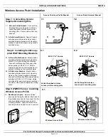
6
3/8” dia hanger wire
mounting holes
(8 places)
3/8” dia hanger wire
mounting holes
(8 places)
Step 6: Hanging Enclosure in Bracket
Step 5: Installing Enclosure in Bracket
5.1 Insert enclosure into bracket as shown align hinges with the
hinge slots in bracket.
5.2 Secure the four sides of the enclosure to the bracket with (4)
#6-32 screws on each side provided with the bracket as
shown.
5.1
5.2
Hinge
Hinge Slot
#6-32 Screws (supplied
with ceiling brackets)


