background image

DP

O

E™

 Power System User Manual 


Part Number: PN380C 


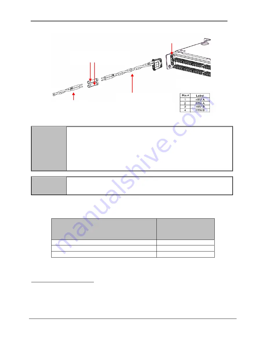
Butt splices connectors  

Power connector 
housing with wire leads  

48VDC 
Supply 

Power Connector on rear side of 

DP

O

E™

 Power Patch Panel or 

Compact 8 Midspan 


Connector 
pinouts 


Figure 4: Connecting to a 

DPoE

™ Power Patch Panel or Compact 8 Midspan 


NOTE: 

The included power harness has two wires for the A-feed power only (pins 1 & 2).  
The 

DP

O

E™

 Power Patch Panel or Compact 8 Midspan supports an optional 

redundant B-feed power option, but the terminals and wire leads are not attached to 
the power harness. 
 
Contact 

PANDUIT

 Technical Support for more information about connecting the 

redundant B-Feed power. (

PANDUIT

 part # DPOEPWRDUAL should be used for 

redundant powering options) 


WARNING: 

The power supply connections on the 

DP

O

E™

 Power Patch Panel and the 

Compact 8 Midspan are polarized. They will not function if power is wired 
improperly. 


Table 5: Minimum Recommended DC AWG for 90°C Cabling for Unprotected 

Outputs  


Total Rectifier Current Rating (A) 

Wire and Lug Gauge 

(AWG) using 90

°

 C wire  


(NEC Table 310.16)

1


10 16 
20 14 
25 12 


1

  Table 310.16 uses Table 3B – Sizes of Conductors from BS EN 60950:2000, “Safety of Information 

Technology Equipment,” December 2000 for non-building wiring. 


6


Содержание DPOE

Страница 1: ...rding or otherwise without written permission from PANDUIT No patent liability is assumed with respect to the use of the information contained herein Although every precaution has been taken in the preparation of this book PANDUIT assumes no responsibility for errors or omissions Neither is any liability assumed for damages resulting from the use of the information contained herein Part PN380C Pub...

Страница 2: ...undesired operation WARNING Changes or modifications to this unit not expressly approved by the party responsible for the compliance could void the user s authority to operate this equipment WARRANTY Unless otherwise specified all products presented in this user s guide are warranted against defects in material and workmanship for a period of one year from the date of invoice by PANDUIT Corp to th...

Страница 3: ... direct indirect special incidental or consequential damages whether based on contract tort or other legal theory Unless otherwise specified by PANDUIT Corp opening this product by unauthorized personnel will void this warranty TRADEMARKS DPOE and Contour Crimp are trademarks of PANDUIT Corporation All other trademarks are the property of their respective owners ...

Страница 4: ...rcuit and Current Limit 11 TROUBLESHOOTING 12 Figures Figure 1 Top View of Power Chassis with Power Rectifiers Installed 1 Figure 2 Individual AC Feed Wiring Architecture 4 Figure 3 DC Wire Diagram 5 Figure 4 Connecting to a DPoE Power Patch Panel or Compact 8 Midspan 6 Figure 5 Chassis Front View 8 Figure 6 Optional Rack Mount Shelf 8 Figure 7 Cord Bracket 9 Figure 8 Chassis Rear View AC Connecti...

Страница 5: ...80C v Table 4 Recommended AC Circuit Breaker and Wire Sizes 4 Table 5 Minimum Recommended DC AWG for 90 C Cabling for Unprotected Outputs 6 Table 6 Recommended Torque Settings 7 Table 7 PANDUIT Corp Contact Information 7 Table 8 Troubleshooting 12 ...

Страница 6: ...pan However 120 watts may not be enough power to support all the Powered Devices PD connected to the panel or powered midspan In these cases or in cases of multiple DPOE Power over Ethernet Systems a larger power system is often required One option is to use the DPOE Power System Chassis with Power Rectifiers herein referred to as the DPOE Power System The DPOE Power System uses a modular design t...

Страница 7: ...uits are shown in Table 5 Minimum Recommended DC AWG for 90 C Cabling for Unprotected Outputs respectively In practice loop voltage drop considerations will usually dictate larger than minimum safe wire size For connection and mounting torque requirements see Table 6 Recommended Torque Settings PANDUIT Corp does not recommend shipping the chassis with the rectifiers installed Rectifiers should be ...

Страница 8: ...um and typical British Thermal Units per hour BTU hr of heat dissipated from each rectifier The maximum is calculated at 90 VAC and typical is calculated at 230 VAC Table 3 Heat Dissipation Part Number Typical BTU hr Max BTU hr DPoEPWRR500 249 410 DPoEPWRR1250 451 833 AC Input Wiring The DPOE Power System chassis uses an individual AC feed architecture See Figure 2 Individual AC Feed Wiring Archit...

Страница 9: ...Output Wiring Sizing There are two main considerations for sizing DC wire ampacity and voltage drop Ampacity refers to the safe current carrying level as specified by U S based organizations such as Underwriters Laboratories and the National Fire Prevention Association which publishes the National Electric Code NEC Voltage drop is simply the amount of voltage loss in a length of wire due to ohmic ...

Страница 10: ...ction may be used as a battery input or as an unfused bulk output The connections require a terminal lug 1 4 single hole lug with a max tongue width of 0 63 or less such as PANDUIT part LCA4 14 L Size wires based on the total rectifier capacity and choose conductor size according to Table 5 Minimum Recommended DC AWG for 90 C Cabling for Unprotected Outputs Connecting to a DPoE Power Patch Panel o...

Страница 11: ...re not attached to the power harness Contact PANDUIT Technical Support for more information about connecting the redundant B Feed power PANDUIT part DPOEPWRDUAL should be used for redundant powering options WARNING The power supply connections on the DPOE Power Patch Panel and the Compact 8 Midspan are polarized They will not function if power is wired improperly Table 5 Minimum Recommended DC AWG...

Страница 12: ...r System note any physical package damage that could indicate potential damage to the contents After removing the DPOE Power System from the boxes and packing material inspect for shipping and or other damage Any problems should be reported to PANDUIT technical support Table 7 PANDUIT Corp Contact Information PANDUIT Technical Support Fax 1 708 444 6993 E mail cs panduit com PANDUIT Product Instal...

Страница 13: ...g the DPOE Power System chassis with mounting screws in the front an optional rack mount shelf may be installed underneath the chassis on the backside of the rack to alleviate potential sagging of the chassis unit due to weight distribution when mounted on a 2 post rack PANDUIT offers a 1RU shelf part SRM19FM1 with a load rating of 30 lbs that will help support the chassis For optimum saftety a 2 ...

Страница 14: ...t Figure 8 Chassis Rear View AC Connections 4 40 Screws Figure 9 Securing Cord Bracket to Chassis DC Output DC connections are accomplished via the rear terminal blocks and bulk output connection as shown in Figure 12 Chassis Rear View DC Connections GMT fused connections are accomplished via the rear compression screw terminal block that will accept wires sizes up to 12 AWG If a fuse is not in co...

Страница 15: ...are available from PANDUIT Corp The bulk output terminals feature a break off plastic piece to prevent inadvertent contact with the terminals If using the bulk DC output feature carefully break off each plastic tab before securing the terminal lugs Size wires based on the total rectifier capacity and choose conductor size according to Table 5 Minimum Recommended DC AWG for 90 C Cabling for Unprote...

Страница 16: ...h the backplane While pressing the latch button down use the latch handle to gently ease the rectifier into the rear connector When the rectifier is properly seated releasing the latch button will hold the latch handle in place WARNING The latch handle must be open for installation or removal of a rectifier Attempting to install a rectifier with the latch handle closed will result in mechanical da...

Страница 17: ...ors are properly mated Table 8 Troubleshooting Alarm Problem Possible Solution DC OK LED is extinguished This rectifier has stopped outputting power Rectifier failed Replace this unit AC OK and all LEDs are extinguished Commercial power has been lost to the specified rectifier s Reset commercial circuit breaker to the dedicated AC circuit that feeds the system Seek alternative power source until p...

Отзывы: