

INSTALLATION INSTRUCTIONS
© Panduit Corp. 2011
PN282D
E-mail:
Fax:
(708) 444-6993
For Instructions in Local Languages
and Technical Support:
www.panduit.com/resources/install_maintain.asp
Page 2 of 2
www.panduit.com
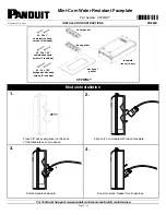
7.
8.
5.
Faceplate Installation
After cables have been aligned, close cover and secure with
#6-32 x 1.25" combination head screws or #6-32 x 1.25"
hexagon button head screws at a max torque of 14 in-lbs.
For hexagon button head screws use a 5/64" hex key tool.
channel
Insert compatible plugs into modules. Align cables
1 per channel on the base gasket as shown above.
After modules have been installed, align #6-32 x 1"
combination head screws with holes as shown above
to mount faceplate. When inserting screws make sure
back seal gasket is properly aligned behind the base.
Press the cover gasket (A) into the cover and the
base gasket (B) into the base as indicated above.
6.
A
B


