Battery Pump CT-2902BPHP
HE17600_C © 09/2016
Intended Use
I.V
authorised
copy
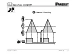
3.5 Description of cutting cycles
When cutting, the cables/conductors must be positioned into the cutting head in a way that the position of the cutter
does not change during the cutting cycle. To avoid shearing forces during the cut, the blades have to approach the
cable/conductor vertically in a 90° angle.
During the cut, the blades approach the cable simultaneously.
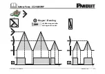
Guillotine type cutters must be closed safely after inserting the cable, before the cutting cycle is initiated by actuating
the trigger. The moveable blade approaches the cable, resp. the stationary blade in a linear movement.
3.6 Description of punching cycles
A punching cycle is characterized by drawing the die into the matrice. The die has to contact the sheet metal prior to
starting the punching cycle.
After terminating the punching cycle the pump switches off automatically to avoid damaging punch and matrice by
unintened contact.
Attention
With thin sheet metals and soft materials (e.g. plastics) the automatic switch o
ff
can not be guaranteed and
the user has to stop the process manually.
3.7 Description of the function of the pump in conjunction with the bus bar tool centre
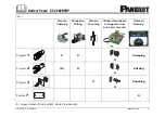
When operating the pump with the Bus Bar Tool Center (note: Adapter SBZ4 is necessary) the forward and return key
is deactivated. The Adapter SBZ4 must be connected to the pump via the remote control socket which has two output
sockets. The fi rst output socket must be connected to the remote controls CT-2902RPS, FTA4 or ZST4. The second
output socket must be connected to the initiator (approach switch) of the bus bar tool center. The initiator must always
be loaded respectively and pushed in the intended position.
For further instructions please read the instruction manual of the Bus Bar Tool Center.
2

