

PROGRAMMING THE SYSTEM
Entering the programming menu, entering the
PIN-code
To change the system settings and program the system using a
computer or the VALET button, the system must be in the
programming mode. Enter the programming mode by entering
the ‘Service PIN-code’ (factory preset is 1-1-1-1).The PIN-code
should be entered using an external or located on the base unit
VALET button. The input is indicated by flashes of an external or
located on the base unit LED indicator. You can enter the code
only if the base unit is powered form USB socket or from an
external power supply, the ignition is switched off, the system is
disarmed and the service mode is switched off.
WARNING!
If there is no ‘Service PIN-code’, you can enter
the programming mode using the ‘Secret PIN-code’
written on the owner’s card.
Entering the PIN-code
• Enter the first digit of the code using the VALET button. Press
the button a number of times, equals to the first digit.
Pauses between presses should not exceed 1 second. Each
pressing will be confirmed with an orange LED indicator
flash. A pause for more than 1 second and a red LED
indicator flash confirm the input of the first digit. Then you
can enter the next digit.
• Enter the second digit of the code using the VALET button.
Press the button a number of times, equals to the second
digit. Pauses between presses should not exceed 1 second.
Each pressing will be confirmed with an orange LED
indicator flash. A pause for more than 1 second and a red
LED indicator flash confirm the input of the second digit.
Then you can enter the next digit.
• Enter the third digit of the code using the VALET button.
Press the button a number of times, equals to the third digit.
Pauses between presses should not exceed 1 second. Each
pressing will be confirmed with an orange LED indicator
flash. A pause for more than 1 second and a red LED
indicator flash confirm the input of the third digit. Then you
can enter the next digit.
• Enter the fourth digit of the code using the VALET button.
Press the button a number of times, equals to the fourth digit.
Pauses between presses should not exceed 1 second. Each
pressing will be confirmed with an orange LED indicator flash.
The system will confirm the correct PIN-code with the series of
red and green flashes and the system will enter the
programming mode. If the input was incorrect, it will be
indicated with a red LED indicator flash and the system will
stay in the previous state. New input can be attempted after 5
seconds.
Status indicator lights during PIN-code entering:
Exit the programming mode
There are several ways to exit the programming mode:
· Switch on the ignition
· Press and hold the VALET button more than 10 seconds
(until a siren sound)
· Disconnect power of the base unit (disconnect the main
power supply and USB)
The system will reboot programmatically (all changes will be
Level 2 – Changing the factory preset of the service PIN-code
Prepare a new value of the ‘Service PIN-code’, it should
consist of 4 digits (from 1 to 9). Write down or remember the
new PIN-code.
Enter the programming menu and then press the VALET button
twice. The system will enter ‘Changing the Service PIN-code’ mode
and the status LED indicator will turn off.
Changing the ‘Service PIN-code’
• Enter the first digit of the code using the VALET button. Press the
button a number of times, equals to the first digit. Pauses between
presses should not exceed 1 second, every pressing will confirm
with an orange LED indicator flash. A pause for more than 1
second and red LED indicator confirms the input of the first digit.
Then you can enter the next digit.
• Enter the other numbers in the same manner. The input of the
fourth number will be confirmed by the series of red and green
LED indicator flashes. The system will wait for PIN-code
re-entering.
• Enter all four digits again.
• If you were able to correctly enter the ‘Service PIN-code’ twice, the
indicator will produce the series of red and green flashes, the new
PIN-code will be recorded, the system will return to programming
mode. In case of the incorrect code input the indicator will be lit
red, the system will return to the programming mode.
Level 3 – Recording the idle speed (rpm) to the system memory
To timely turn off the starter during automatic or remote
engine start via digital or analog tachometer input and the
correct operation of the ‘Smart Turbo Timer’, it is necessary to
record the engine idle speed.
To record the idle speed to the non-volatile system memory, enter
the programming menu. Press the VALET button three times.
Switch on the ignition and start the engine after entering this level
of programming (the engine should be warmed-up; idle speed
should match the stable idle speed of the warmed-up engine).
The system will confirm the presence of the idle speed status with
green flashes of the LED indicator. Wait until the stable idle speed
will be reached and save the changes.
Saving changes:
Press the VALET button once to save idle speed. Successful
recording of the idle speed will be confirmed with the series of red
and green flashes of LED indicator and a siren signal. The series of
siren signals will indicate incorrect recording. The system will exit
the programming menu and reboot after saving the idle speed.
Level 4 – Resetting to the factory settings
The procedure recovers the factory settings of the system
without deleting previously registered devices (remote
controls, tags, mobile device, relays, etc.) that is stored in the
non-volatile memory.
To reset the settings enter the programming
mode and press the VALET button four times. Press and hold the
VALET button for more than 4 seconds until a siren signal, then
release the button. The system will confirm resetting to the factory
settings with a long red flash of the LED indicator. After that the
system will return to the programming mode.
Level 5 – Recording a Bluetooth engine compartment module
(RHM-03BT)
To record a Bluetooth engine compartment module, enter the
programming mode and press the VALET button 5 times. The LED
indicator will light green and the system will enter the recording of
an engine compartment module mode.
An example of recording an engine compartment module is on the
reverse side.
Level 6,7 – Recording Bluetooth radio relays №1, №2 (BTR-101)
Radio relays recording is performed one by one starting from the
6th level: a radio relay №1 is recorded on the 6th level; a radio relay
№2 is recorded on the 7th level. Enter the required level and the
system will enter the recording of a radio relay mode.
An example of recording radio relays is on the reverse side.
Level 8 – Recording a Bluetooth GPS/GLONASS receiver
(NAV-035BT)
To record a Bluetooth GPS/GLONASS receiver, enter the
programming mode and press the VALET button 8 times. The LED
indicator will light green and the system will enter the recording of
a receiver.
An example of recording a GPS/GLONASS receiver is on the
reverse side.
saved) after exiting programming mode. All ways to exit the
programming menu are accompanied by sound signals of the
siren and light signals of the LED indicator. The signals indicate the
number of recorded control devices.
Indication of recorded control devices:
Preparing to program the system using a computer
The system allows programming all settings and updating
software of the base unit via a USB cable. If the base unit has not
been installed in the vehicle yet, it will be powered from a USB
cable while programming. To program using a computer, you
need a standard USB cable, a computer with Windows
XP/Vista/7/8/10 and the Pandora Alarm Studio application (you
can download it from pandorainfo.com). It is required to create an
account in the Alarm Studio to use the Pandora CLONE for remote
engine start (you can register without a connection to the
system). The Pandora CLONE procedure requires an Internet
connection.
In preparation to programming, these stages should be
followed:
• Install the Pandora Alarm Studio
• Start the Pandora Alarm Studio
• Connect the system and PC via a USB cable
• Enter the programming mode by entering the service PIN-code
• The application will automatically open
Updating firmware
It is recommended to update firmware of the base unit before
installing and programming the system (actual version of the
firmware you can download from pandorainfo.com or from the
Alarm Studio). You can update firmware using the Alarm Studio
application after entering the programming mode.
Programming using the VALET button
The system allows programming some settings using the VALET
button. To configure all settings use a computer to program the
system.
Enter the programming mode by entering the «Service PIN-code».
Use the VALET button to enter the desired level number (press the
button the number of times, equals to the level number; pauses
between presses should not exceed 1 second). The system will
confirm correct input with red LED flashes and short sound
signals of a siren and proceed to the desired level. If the input was
incorrect, the system will not confirm input and will await a new
level input after a series of green and red flashes.
Level 1 – Recording remote controls/radio tags into the system
memory
Prepare to record all remote controls (system memory cells are
designed for four 868MHz remote controls and one 2.4GHz
remote control. The D-800 remote control uses 2 cells – 1 for
868MHz and 1 for 2.4 GHz) and radio tags (you can record up to
3 tags). Insert batteries in the remote controls and radio tags. If
the main remote control is switched off, switch it on in
accordance with its manual.
Enter the programming menu and then press the VALET button
once. The LED indicator will light green and the system will enter the
remote controls and tags recording mode.
An example of recording remote controls and radio tags is on
the reverse side.
Level 11 – Programming and configuring an “Immobilizer
PIN-code”
It is necessary to configure an analog input (INP) as ‘Code
immobilizer’ in the settings of the base unit inputs when
implementing the “Code immobilizer” function via an
analog input. It may be necessary to switch on the
ignition after entering the level 11 of programming (if
the car bus is active only when the ignition is switched
on) when implementing the “Code immobilizer” via a
digital CAN-bus protocol.
To program an “Immobilizer PIN code”, enter the
programming mode and press the VALET button 11 times.
The level is divided into 3 sublevels (Sublevel 11.1 – Selecting
buttons; sublevel 11.2 entering the PIN-code; sublevel 11.3 –
confirmation of the PIN-code input). The system will
automatically enter the sublevel 11.1 (Selecting buttons) after
entering the level 11. The system can determine buttons via
an analog “Code immobilizer” input or via a digital protocol of
a car. After selecting active buttons enter the sublevel 11.2
(Entering PIN-code) by pressing the VALET button once.
Program the PIN-code using the selected buttons at this
sublevel; press the VALET button once and enter the PIN-code
again. To confirm PIN-code re-entering and save all the
settings press the VALET button once again.
Sublevel 11.1 - Selecting buttons:
This sublevel is used to select active buttons via a digital
protocol of a car or via a ‘Code Immobilizer’ analog input. To
determine the activity of an analog “Code Immobilizer” input,
apply potential to the corresponding input (INP) of the base
unit, the LED indicator will be flashing orange. If you
determine buttons via a digital protocol select one or more
buttons (up to four) for entering the secret code of the
immobilizer. To do this press the selected button, the LED
indicator will confirm input with orange flashes. If there are
no orange flashes when any button is pressed, then this
button is not recognized by the system, select a different
button. Repeat the procedure to select the second, third,
fourth button and enter the next sublevel. To enter the next
sublevel 11.2l press the VALET button once.
Sublevel 11.2 – Entering the PIN-code:
Program the immobilizer deactivation PIN-code using the
selected button or buttons. Enter the first digit by pressing the
previously selected button (pauses between presses should
not exceed 1 second). The base unit will confirm entering with
a red flash of the LED indicator. Enter the second (third, fourth)
digit by pressing the previously selected button. The base unit
will confirm entering of each digit with a red flash of the LED
indicator. Input the required number of digits (up to 4) and
then press the VALET button. The system will confirm receiving
of the secret validator code with a long red flash of the LED
indicator and will wait for confirmation of the PIN-code.
Sublevel 11.3 - Confirmation of the PIN-code input:
Enter the PIN-code again similarly to the procedure (level 11.2
– Entering PIN-code) and press the VALET button. The system
will confirm the correct PIN-code with red and green flashes
of the LED indicator and will memorize the PIN-code, and then
the system will proceed to the programming mode awaiting
level input. Incorrect confirmation is indicated with a long red
flash of the LED indicator, after that the system will return to
the programming mode.
Level 15 – Emergency deactivating immobilizer radio tags
To disable/enable immobilizer tags, enter the programming menu
and press the VALET button 15 times. The LED indicator will light
green (green light indicates enabled tag) and the system will wait
for “Secret PIN-code” entering. Red light of the LED indicates
disabled immobilizer tag.
Disabling radio tags:
The LED indicator will light green after entering the programming
level. The system will wait for entering the ‘Secret PIN-code’. Enter
the ‘Secret PIN-code’ that is written on the owner’s plastic card.
The system will confirm disabling of the radio tag with two sound
signals of the siren and a long red LED flash. After that the system
will return to the programming menu. If the PIN-code is not
entered within 10 seconds or the input is incorrect, a siren will
sound one signal, the LED will produce the series of red and green
flashes and the system will return to the programming menu.
Enabling radio tags:
The LED indicator will light red after entering the programming
level. The system will wait for an action. Press the VALET button
once to enable radio tags. The system will confirm enabling with
one short sound signal of a siren and a green LED light. After that
the system will return to the programming menu.
Level 16 – Updating firmware of the built-in Bluetooth modem
Download firmware and install the Pandora BT application
on your mobile device (Android or iOS with Bluetooth 4.0
Low Energy or higher support).
To update firmware of the built-in Bluetooth modem, enter the
programming mode and press the VALET button 16 times. Find
your system in the mobile application, go to detected devices and
select one of the updating option: File manager (for Android only)
or Internet and update Bluetooth modem firmware. File manager
allows to upload firmware from phone storage and Internet option
allows to upload Firmware from the server to the base unit.
Level 17 – Programming bypass of an original immobilizer
Bypass learning procedure is performed on this level.
Detailed manuals can be found in the Alarm Studio.
Level 18 – Pairing and unpairing a mobile device
The system supports only one mobile device. Pairing a new
mobile device (if the system has previously paired device) is
not allowed without unpairing procedure. When you
overwrite the same device in the system memory, you should
delete the Bluetooth connection on your mobile device,
delete the mobile device from the system memory and then
record the mobile device in the system memory.
To pair a mobile device, enter the programming mode and press
the VALET button 18 times. The LED indicator will light green (a
green light indicates the system is ready to pair a mobile device)
and the system will enter the mobile device pairing mode. A red
light of the LED indicates the system has already had paired mobile
device, overwriting of the mobile device can be done only after
unpairing procedure.
An example of recording a mobile phone is on the reverse
side.
Level 23, 24 – Recording door sensors №1, №2 (DMS-100BT)
Door sensors recording is performed one by one starting from the
23rd level: A door sensor №1 is recorded on the 23rd level; a door
sensor №2 is recorded on the 24th level. A door sensor can be
overwritten only on the level of its initial registration. To record
door sensors №1, №2, enter the programming mode and press
the VALET button 23 times for the door sensor №1 or 24 times for
the door sensor №2. The LED indicator will light green and the
system will enter the recording a door sensor mode.
An example of recording door sensors is on the reverse side.
Level 27 – Recording additional modules (DI-04, BT-01)
The system supports only one device DI-04 or BT-01.
To record an additional device, enter the programming mode and
press the VALET button 27 times. The LED indicator will light green
and the system will enter the recording mode.
An example of recording is on the reverse side.
Level 19, 20, 21, 22, 25, 26, 28 – Updating firmware of additional
Bluetooth devices
Download the firmware and install Pandora BT application
on your mobile device.
To update firmware of additional devices, enter the programming
mode and press VALET button the number of times equals to the
desired level number (see the Programming levels table). Find
your system in the mobile application, go to detected devices and
select one of the updating option: File manager (for Android only)
or Internet and update firmware. File manager allows to upload
firmware from phone storage and Internet option allows to
upload Firmware from the server to the base unit.
FUEL LEVEL CALIBRATION
Warning!
This procedure is used only in case of analog
connection.
Make a connection in of the «Fuel level input» to an original fuel
sensor Enable the “Use INP (+) to control fuel level” setting in the
Alarm Studio.
• Start the engine
• Call the system number and wait for the answer
• Dial 424* command (Fuel level calibration). The system will confirm
the input of the command.
• Dial a DRMF command (use values from the table below, it depends
on the current fuel level). The system will confirm the input of the
command.
• End the call.
FUEL LEVEL CALIBRATION TABLE (424*)
DTMF command
Fuel level
0*
0%
10*
10%
20*
20%
25*
25%
30*
30%
40*
40%
50*
50%
60*
60%
70*
70%
75*
75%
80*
80%
90*
90%
100*
100%
888*
Reset all calibration values
v.1.1
LED signal
Description
Short orange flashes
Number of recorded remote controls
Short green flashes
Number of recorded radio tags
Long red flash
Mobile phone is paired
LED signal
Short orange flash
Confirmation of the VALET button pressing
Short red flash
Confirmation of entering a PIN-code digit
Red and green flashes PIN-code is correct
Long red flash
PIN-code is incorrect
Description
RHM-03 BT
2
5
1
4
NO
NC
COM
Programming
6
Antenna 2.4 GHz
+12V
3
BTR-101
Connection
1
Red
2
Black
+12В
GND
TOP SIDE
GPS-antenna
NAV-035 BT
Place the radio module
unit wires down. Do not
shield the zone of the built
antenna (no less than 3 cm
from metal surfaces)
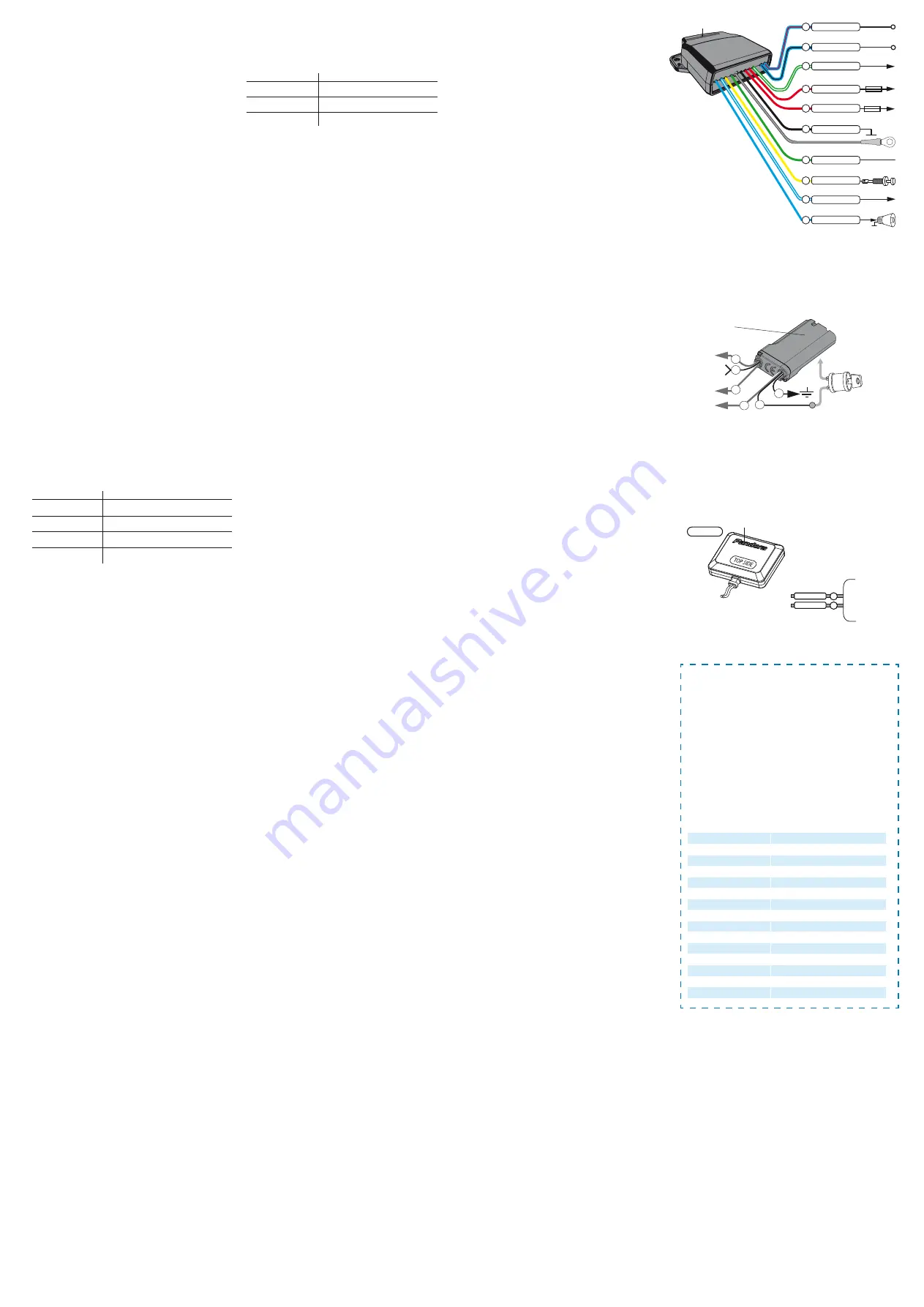
Antenna 2.4 GHz
Front hood switch
(-)
+12V
15A*
3A*
Siren
2A (+)
LIN output/Programming
Blocking relay (NC)
To front hood lock (Closing)
To front hood lock (Opening)
Front hood lock circuit power
supply
+12V Module power supply
Blocking relay (COM)
10A
Blue/Red
Blue/Black
Green/White
Red
Red
Black
Green
Yellow
Blue/White
Blue
10
9
8
7
6
5
4
3
2
1
Temperature sensor


