


Panasonic Corporation
Automation Controls Business Unit
industrial.panasonic.com/ac/e
ACCTB13E 201201-T
NOTES FOR USING FPC CONNECTORS
(Common)
PC board design
Design the recommended foot pattern in
order to secure the mechanical strength
in the soldered areas of the terminal.
FPC and equipment design
Design the FPC based with
recommended dimensions to ensure the
required connector performance.
Due to the FPC size, weight, or the
reaction force of the routed FPC.
Carefully check the equipment design
and take required measures to prevent
the FPC from being removed due to a fall,
vibration, or other impact.
Connector mounting
Excessive mounter chucking force may
deform the molded or metal part of the
connector. Consult us in advance if
chucking is to be applied.
Soldering
1) Manual soldering.
• Due to the connector’s low profile, if an
excessive amount of solder is applied
during manual soldering, the solder may
creep up near the contact points, or
solder interference may cause imperfect
contact.
• Make sure that the soldering iron tip is
heated within the temperature and time
limits indicated in the specifications.
• Flux from the solder wire may adhere to
the contact surfaces during soldering
operations. After soldering, carefully
check the contact surfaces and clean off
any flux before use.
• Be aware that a load applied to the
connector terminals while soldering may
displace the contact.
• Thoroughly clean the iron tip.
2) Reflow soldering
• Screen-printing is recommended for
printing paste solder.
• To determine the relationship between
the screen opening area and the PC
board foot pattern area, refer to the
diagrams in the recommended patterns
for PC boards and metal masks when
setting.
• Note that excess solder on the terminals
prevents complete insertion of the FPC,
and that excess solder on the soldering
terminals prevents the lever from rotating.
• Screen thickness of 120
µ
m is
recommended for paste solder printing.
• Consult us when using a screen-printing
thickness other than that recommended.
• Depending on the size of the connector
being used, self alignment may not be
possible. Accordingly, carefully position
the terminal with the PC board pattern.
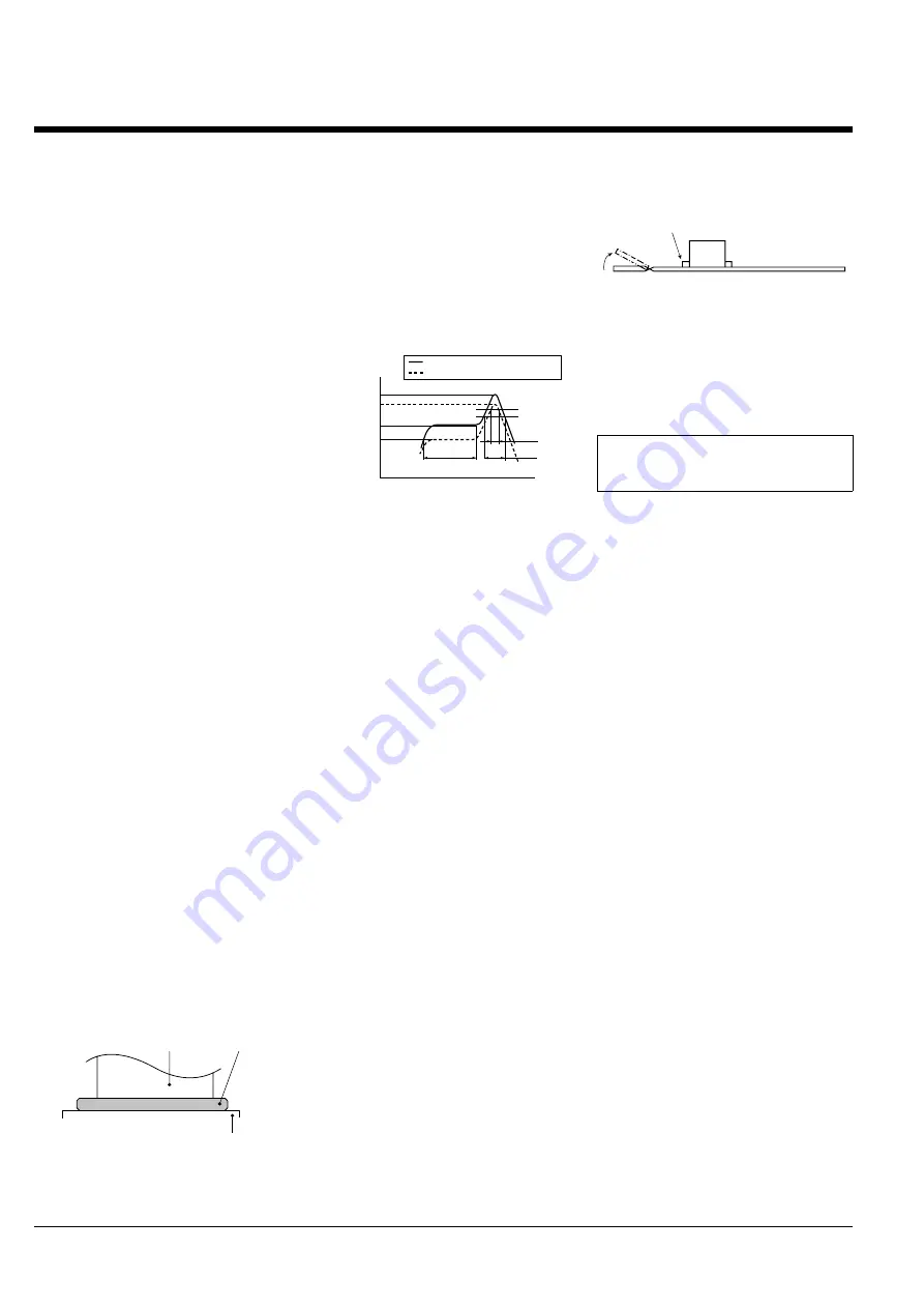
• The recommended reflow temperature
profile is given in the figure below
Recommended reflow temperature
profile
• The temperature is measured on the
surface of the PC board near the
connector terminal.
• Certain solder and flux types may cause
serious solder creeping. Solder and flux
characteristics should be taken into
consideration when setting the reflow
soldering conditions.
• When performing reflow soldering on
the back of the PC board after reflow
soldering the connector, secure the
connector using, for example, an
adhesive. (Double reflow soldering on the
same side is possible)
3) Reworking on a soldered portion
• Finish reworking in one operation.
• For reworking of the solder bridge, use
a soldering iron with a flat tip. Do not add
flux, otherwise the flux may creep to the
contact parts.
• Use a soldering iron whose tip
temperature is within the temperature
range specified in the specifications.
Do not drop or handle the
connector carelessly. Otherwise, the
terminals may become deformed due
to excessive force or applied
solderability may be during reflow
degrade.
Don’t open/close the lever or insert/
remove an FPC until the connector is
soldered. Forcibly applied external
pressure on the terminals can weaken
the adherence of the terminals to the
molded part or cause the terminals to
lose their evenness. In addition, do
not insert an FPC into the connector
before soldering the connector.
When cutting or bending the PC
board after mounting the connector,
be careful that the soldered sections
are subjected to excessive forces.
Other Notes
When coating the PC board after
soldering the connector (to prevent the
deterioration of insulation), perform the
coating in such a way so that the coating
does not get on the connector.
The connectors are not meant to be used
for switching.
Terminal
Paste solder
PC board foot pattern
150
°
C
180
°
C
230
°
C
220
°
C
200
°
C
260
°
C
Temperature
Upper limit (Soldering heat resistance)
Lower limit (Solder wettability)
Preheating
Peak temperature
Time
25 sec.
70 sec.
60 to 120 sec.
Please refer to the latest product
specifications when designing your
product.
The soldered areas should not be subjected to forces.