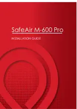
3. Install the inner shell.
Slide the covers located on the both lateral
sides of the camera and put the inner shell on
the camera until the hooks inside the inner shell
are held in the holes of the camera (until a click
is heard).
Important:
Put the inner shell down on the cam-
era until the outside cover of the camera
cannot be seen from the opening (from
which the camera lens is visible) of the inner
shell. If this integration is not successfully
performed, the inner shell may be removed
or the hidden part at the top of the screen
may become larger in the WIDE mode.
How to remove the inner shell
Press the inner shell from the front and rear
sides inward (at the same vertical position as
the hooks) to bend the shell and remove the
shell from the camera.
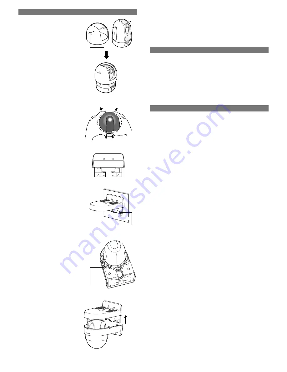
4. Mount the top cover on the wall and run the cables.
Secure the top cover in either of the following
two ways:
q
and
w
. No screw is supplied.
Procure screws according to the installation
area.
q
M4 screws, 4 positions (a)
or
w
M4 screws, 2 positions ((a) upper 2 posi-
tions, not available in lower positions) and
M6 or M8 anchor bolts, 2 positions (b)
Important:
The length of the anchor bolt pro-
jecting portion (the distance between the tip
of the anchor bolt and the chassis attaching
surface) shall be 7 mm {1/4"} or less. Failure
to observe this causes interference between
the anchor bolt and bottom cover. Therefore,
the bottom cover cannot be mounted.
5. Mount the camera.
Refer to "Installations/Connections" in the Instal-
lation Guide of WV-NS202 for further information.
The camera mounting bracket is already
attached to this bracket at the time of purchase.
6. Mount the bottom cover.
Be sure to push the bottom cover up until a click
is heard.
Important:
Do not let the cables be caught dur-
ing installation work.
7. Tighten the fixing screw to be used for cover
fall prevention.
Recommended tightening torque: 1.6 N·m {16 k
g
f·cm}
Cover
Hook
Put on until a click is heard
(a)
(a)
(a)
(a)
(b)
(b)
7 mm {1/4"}
Anchor bolt
Safety wire
Camera fixing screw
Bottom cover
Specifications
Ambient temperature:
–10 °C - +50 °C {14 °F - 122 °F}
Dimensions:
165 (W) x 206.5 (H) x 217.5 (D) mm
{6-1/2" (W) x 8-1/3" (H) x 8-9/16" (D)}
Weight:
Approx. 950
g
{2.10 lbs.}
Finish:
Main body: Treatment steel
Top and bottom covers: ABS resin with silver metallic coating
Dome cover: Acrylic resin
Press from the front and rear
sides inward to bend
Standard Accessories
Operating Instructions (this book) ............................. 1 pc.
The following are for installation.
Template .................................................................... 1 sheet
Inner shell .................................................................. 1 pc.
Installations
(continued)
© 2006 Matsushita Electric Industrial Co., Ltd. All Rights Reserved.
For European and other fields:
Matsushita Electric Industrial Co., Ltd.
Osaka, Japan
http://panasonic.net
For U.S., Canadian and Puerto Rican fields:
Panasonic System Solutions Company,
Unit Company of Panasonic Corporation of North America
Security Systems
www.panasonic.com/security
For customer support, call 1.877.733.3689
Executive Office:
Three Panasonic Way 2H-2, Secaucus,
New Jersey 07094
Zone Office
Eastern:
Three Panasonic Way, Secaucus, New Jersey 07094
Central:
1707 N. Randal Road, Elgin, IL 60123
Southern:
1225 Northbrook Parkway, Suwanee, GA 30024
Western:
6550 Katella Ave., Cypress, CA 90630
Panasonic Canada Inc.
5770 Ambler Drive,Mississauga,
Ontario, L4W 2T3 Canada (905)624-5010
http://www.panasonic.ca
Panasonic Sales Company
Division of Panasonic Puerto Rico Inc.
San Gabriel Industrial Park 65th Infantry Ave. KM. 9.5 Carolina
P.R. 00985(809)750-4300
Inner shells
Note:
When the camera lens is pointed in the horizontal direction, the inner shell interferes with
the camera’s view, and consequently about upper half of the monitor screen is hidden in the
WIDE mode.