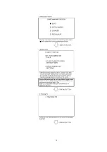
capable of handling 10 kV without causing X-Radiation.
NOTE :
It is important to use an accurate periodically calibrated high
voltage meter.
3. Measure the High Voltage. The meter (electrostatic type) reading
should indicate 2.2 kV±0.1 kV. If the meter indication is out of
tolerance, immediate service and correction is required to prevent
the possibility of premature component failure. To prevent an X-
Radiation possibility, it is essential to use the specified picture
tube.
5. OPERATION GUIDE
6. SERVICE NOTES (PLEASE READ)
6.1. SERVICE NOTES
6.1.1. EXTENSION CABLES FOR SERVICE
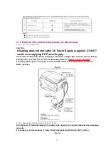
NOTE:
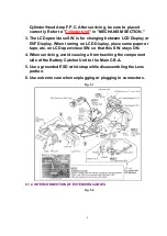
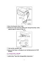
1. When using the cassette tape:
A. Be sure to remove a cassette lid cover of cassette tape.
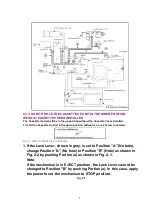
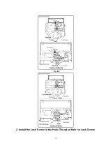
B. Be sure to install the Lock Screw to Cassette Up Unit. After
servicing, be sure to remove the Lock Screw.
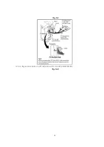
Refer to "
HOW TO HOLD THE CASSETTE UP UNIT IN THE
DOWN POSITION WITHOUT CASSETTE COVER INSTALLED
."
C. Select the H. SAFETY DEFEAT in SERVICE MODE. Refer to "
SERVICE MODE SPECIFICATION (SELF-DIAGNOSTIC SYSTEM)
.
"
Or, connect a silicon diode on component side of the Main
C.B.A. as shown to defeat safety function.
(Since Takeup Reel sensor, located on Main C.B.A. does not
work when opening Main C.B.A., the mechanism does not work
(Reel lock). Therefore, make sure to defeat Safety function.)
2. Use extreme care so as not to apply any excessive pressure to the
7
Содержание VM-D101
Страница 10: ...Fig 2 2 2 Install the Lock Screw in the Hole Threaded Hole for Lock Screw 10 ...
Страница 12: ...12 ...
Страница 13: ...13 ...
Страница 14: ...14 ...
Страница 15: ...15 ...
Страница 16: ...16 ...
Страница 17: ...6 1 5 DESCRIPTION OF EMERGENCY INDICATIONS 17 ...
Страница 22: ...Fig 5 2 6 1 8 4 Signal description on TP Adjustment P C B 40P VFKW0123B Fig 5 3 1 22 ...
Страница 23: ...Fig 5 3 2 23 ...
Страница 24: ...Fig 5 3 3 24 ...
Страница 32: ...7 1 2 2 EVR Cover Side Case L Unit Fig D3 32 ...
Страница 33: ...7 1 2 3 Sensor Shield Case Lens Unit Fig D4 33 ...
Страница 34: ...7 1 2 4 Main C B A Fig D5 7 1 2 5 VCR Mechanism Chassis Ass y Side Case R Unit Fig D6 34 ...
Страница 35: ...7 1 3 LCD PORTION For model with LCD Monitor 7 1 3 1 Cassette Cover Unit Fig D7 1 35 ...
Страница 36: ...7 1 3 2 Relay C B A Cassette Frame Fig D7 2 36 ...
Страница 38: ...7 1 3 6 LCD Lamp Unit Fig D7 6 38 ...
Страница 39: ...7 1 4 SIDE CASE L PORTION 7 1 4 1 EVF Unit Color EVF Unit Fig D8 1 39 ...
Страница 40: ...7 1 4 2 Side L FPC Unit Fig D8 2 40 ...
Страница 41: ...7 1 5 EVF PORTION For model with Monochrome EVF 41 ...
Страница 43: ...7 1 6 COLOR EVF PORTION For model with Color EVF 43 ...
Страница 46: ...Fig D11 2 46 ...
Страница 47: ...7 1 8 LENS PORTION B 7 1 8 1 Lens Piece Unit Fig D12 1 47 ...
Страница 49: ...7 1 9 2 Top Operation Unit Fig D13 2 7 1 9 3 Battery Catcher Unit Fig D13 3 49 ...
Страница 52: ...7 3 2 Inner Parts Location 7 3 2 1 TOP VIEW Fig DM1 1 52 ...
Страница 53: ...7 3 2 2 BOTTOM VIEW Fig DM1 2 7 3 3 STOP Position Confirmation Fig DM2 53 ...
Страница 55: ...Fig DM3 2 55 ...
Страница 56: ...7 3 5 Cylinder Unit Fig DM4 1 1 56 ...
Страница 57: ...Fig DM4 1 2 57 ...
Страница 58: ...7 3 6 Cylinder Head Amp F P C Bugle Chip Fig DM4 2 7 3 7 P C B Angle Fig DM5 58 ...
Страница 59: ...7 3 8 Mechanism F P C Unit Fig DM6 1 59 ...
Страница 60: ...Fig DM6 2 60 ...
Страница 61: ...7 3 9 Tension Unit Reel Table Unit Fig DM7 1 61 ...
Страница 62: ...Fig DM7 2 62 ...
Страница 63: ...7 3 10 Rev Clutch Fig DM8 63 ...
Страница 64: ...7 3 11 Take Gear Rev Brake Arm Unit Fig DM9 1 Fig DM9 2 64 ...
Страница 65: ...7 3 12 A C Head Unit Fig DM10 65 ...
Страница 66: ...7 3 13 Capstan Belt Fig DM11 66 ...
Страница 67: ...7 3 14 Capstan Unit Fig DM12 67 ...
Страница 68: ...7 3 15 Idle Arm Unit Fig DM13 68 ...
Страница 69: ...7 3 16 Mechanism Support Angle Fig DM14 69 ...
Страница 70: ...7 3 17 Reduction Gear B Fig DM15 7 3 18 Reduction Gear A Reduction Gear Unit Fig DM16 70 ...
Страница 71: ...7 3 19 Pinch Arm Unit Opener P5 Arm Unit Fig DM17 1 Fig DM17 2 71 ...
Страница 72: ...7 3 20 Takeup Post Unit Supply Post Unit Fig DM18 1 72 ...
Страница 73: ...Fig DM18 2 73 ...
Страница 74: ...7 3 21 Impedance Roller Unit Loading Base Unit Fig DM19 1 74 ...
Страница 75: ...Fig DM19 2 75 ...
Страница 76: ...7 3 22 Takeup Loading Arm Unit Fig DM20 76 ...
Страница 77: ...7 3 23 Supply Loading Arm Unit Fig DM21 1 77 ...
Страница 78: ...Fig DM21 2 78 ...
Страница 79: ...Fig DM21 3 79 ...
Страница 80: ...7 3 24 Loading Motor Unit Main Cam Unit Pinch Toggle Fig DM22 80 ...
Страница 81: ...7 4 SCREWS FOR DISASSEMBLY ASSEMBLY OF MECHANISM 8 ADJUSTMENT PROCEDURES 8 1 SERVICE FIXTURES TOOLS 81 ...
Страница 94: ...For necessary equipments marked s in Fig E1 2 and E1 3 refer to the following table 94 ...
Страница 105: ...12 2 FRAME SECTION 1 105 ...
Страница 106: ...12 3 FRAME SECTION 2 Model PV D301 VM D101 106 ...
Страница 107: ... Model PV L501 PV L551 PV L561 PV L581 PV L51 PV L601 PV L651 PV L661 PV L681 PV L61 VM L451 107 ...
Страница 108: ...12 4 COLOR EVF SECTION Model PV D301 PV L551 PV L561 PV L581 PV L51 PV L601 PV L651 PV L661 PV L681 PV L61 VM L451 108 ...
Страница 109: ...12 5 EVF SECTION Model VM D101 PV L501 109 ...
Страница 110: ...12 6 PACKING PARTS AND ACCESSORIES SECTION 110 ...


