


1 Safety Precautions
1.1.
General Guidelines
1. When servicing, observe the original lead dress. If a short circuit is found, replace all parts which have been overheated or
damaged by the short circuit.
2. After servicing, see to it that all the protective devices such as insulation barriers, insulation papers shields are properly
installed.
3. After servicing, make the following leakage current checks to prevent the customer from being exposed to shock hazards.
4. When servicing, observe the original lead dress. If a short circuit is found, replace all parts which have been overheated or
damaged by the short circuit.
5. After servicing, see to it that all the protective devices such as insulation barriers, insulation papers shields are properly
installed.
6. After servicing, make the following leakage current checks to prevent the customer from being exposed to shock hazards.
1.2.
Touch-Current Check
1. Plug the AC cord directly into the AC outlet. Do not use an isolation transformer for this check.
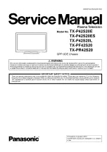
2. Connect a measuring network for touch currents between each exposed metallic part on the set and a good earth ground
such as a water pipe, as shown in Figure 1.
3. Use Leakage Current Tester (Simpson 228 or equivalent) to measure the potential across the measuring network.
4. Check each exposed metallic part, and measure the voltage at each point.
5. Reserve the AC plug in the AC outlet and repeat each of the above measure.
6. The potential at any point (TOUGH CURRENT) expressed as voltage U
1
and U
2
, does not exceed the following values:
For a. c.: U
1
= 35 V (peak) and U
2
= 0.35 V (peak);
For d. c.: U1 = 1.0 V,
Note:
The limit value of U
2
= 0.35 V (peak) for a. c. and U
1
= 1.0 V for d. c. correspond to the values 0.7 mA (peak) a. c. and 2.0
mA d. c.
The limit value U
1
= 35 V (peak) for a. c. correspond to the value 70 mA (peak) a. c. for frequencies greater than 100 kHz.
7. In case a measurement is out of the limits specified, there is a possibility of a shock hazard, and the equipment should be
repaired and rechecked before it is returned to the customer.
Measuring network for TOUCH CURRENTS
COLD
WATER PIPE
(EARTH GROUND)
Rs=
1500Q
_ L Cs=
0.22|
j
F
10kQ
-1
k
1
-------
1
Ro=
----------------
J
500Q
'
U
1
=
r
= 0.022|jF
( V )
J Q
L jJ J U U i i
U 1 — |— и . и ^ г ф Г
^ V
J
| U
2
(V)
APPLIANCES
EXPOSED
METAL PARTS
Resistance values in ohms (Q)
V:
Voltmeter or oscilloscope
(r.m.s. or peak reading)
Input resistance:
> 1 MQ
Input capacitance: < 200 pF
Frequency range: 15 Hz to 1 MHz and d.c. respectively
NOTE - Appropriate measures should be taken to obtain the correct value in case of non-sinusoidal waveforms.
Figure 1
3
Содержание Viera TX-P42S20E
Страница 21: ...7 4 No Picture 21 ...
Страница 33: ...11 Block Diagram 11 1 Main Block Diagram 33 ...
Страница 34: ...11 2 Block 1 4 Diagram 34 ...
Страница 35: ...G 0 11 3 Block 2 4 Diagram I A I D IG IT A L S IG N A L P R O C E S S O R 35 ...
Страница 36: ...11 4 Block 3 4 Diagram P P O W E R S U P P LY 36 ...
Страница 37: ...11 5 Block 4 4 Diagram s c s c a n d r i v e s s s u s t a i n d r i v e 37 ...
Страница 38: ...38 ...
Страница 40: ...12 3 Wiring 2 40 ...
Страница 43: ...13 2 P Board 1 4 Schematic Diagram A B C D E A P BO ARD LSEP1287BE HB 1 4 F 1 2 3 4 42 ...
Страница 44: ...13 3 P Board 2 4 Schematic Diagram A P BO ARD LSEP1287BE HB 2 4 10 11 12 13 14 15 16 17 18 43 ...
Страница 45: ...13 4 P Board 3 4 Schematic Diagram A B C D E F 1 2 3 4 44 ф ф 5 ...
Страница 46: ...13 5 P Board 4 4 Schematic Diagram 10 11 12 13 14 15 16 17 18 45 ...
Страница 47: ...13 6 A Board 1 19 Schematic Diagram A A A BO AR D 1 19 IIC B C D E F 1 2 3 4 9 46 ...
Страница 52: ...13 11 А Board 6 19 Schematic Diagram A A BO AR D 6 19 STB MPU 46 47 48 49 ...
Страница 54: ...13 12 А Board 7 19 Schematic Diagram A A BO AR D 7 1 9 HDMI 55 56 57 58 59 52 ...
Страница 57: ...69 70 71 72 ...
Страница 59: ...Peaks COM MON 78 79 80 81 ...
Страница 61: ...13 16 A Board 11 19 Schematic Diagram A A BO AR D 11 19 A V SW 91 92 93 94 95 96 97 98 99 56 ...
Страница 63: ...FE_Virtual_Module Peaks COMMON TO 3 19 Analog ASIC 104 105 106 107 108 57 ...
Страница 65: ...13 19 A Board 14 19 Schematic Diagram A A BO AR D 14 19 PD4H 118 119 120 121 122 123 124 125 126 59 ...
Страница 68: ...140 141 142 143 144 61 ...
Страница 71: ...63 ...
Страница 72: ...13 24 A Board 19 19 Schematic Diagram A A BO AR D 19 19 DVB T C D EM O D U LATO R 64 ...
Страница 75: ...13 27 C2 Board 1 2 Schematic Diagram A A C 2 BO AR D TN PA5095 1 2 ___ I TO A BOARD A32 B 67 ...
Страница 78: ...13 30 SC Board 2 4 Schematic Diagram 10 I 11 1 12 1 13 1 14 1 15 1 16 1 17 1 18 70 ...
Страница 79: ... 13 31 SC Board 3 4 Schematic Diagram 19 1 20 1 21 1 22 1 23 1 24 1 25 1 26 1 27 71 ...
Страница 80: ...13 32 SC Board 4 4 Schematic Diagram 28 29 30 31 32 33 34 35 36 72 ...
Страница 81: ...13 33 SS Board 1 2 Schematic Diagram A B C D E A SS BO AR D TX N S S 11D E K 1 2 F 5 6 7 8 9 73 ...
Страница 86: ...P BOARD COMPONENT SIDE LSEP1287BEHB B G 6 5 4 3 2 1 E F H 77 ...
Страница 88: ...14 3 A Board 6 A BOARD FOIL SIDE A P42S20E A P42S20ES A P42S20L A PF42S20 A PR42S20 B G 5 4 3 2 1 E F H 79 ...
Страница 89: ...A BOARD COMPONENT SIDE A P42S20E A P42S20ES A P42S20L A PF42S20 A PR42S20 B G 6 5 4 3 2 1 E F H 80 ...
Страница 92: ...14 6 SC Board SC BOARD FOIL SIDE TXNSC11DEK B G 6 5 4 3 2 1 E F H 83 ...
Страница 93: ...SC BOARD COMPONENT SIDE TXNSC11DEK B G 6 5 4 3 2 1 E F H 84 ...
Страница 94: ...14 7 SS Board SS BOARD FOIL SIDE TXNSS11DEK B G 6 5 4 3 2 1 E F H 85 ...
Страница 95: ...SS BOARD COMPONENT SIDE TXNSS11DEK ...
Страница 96: ......
Страница 98: ...15 1 2 Exploded View 2 88 ...
Страница 99: ...15 1 3 Packing 1 89 ...
Страница 100: ...15 1 4 Packing 2 90 ...


