6
Servicing method
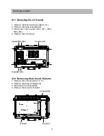
4.3. Removing the switch unit
1. Remove the rear cover(See 5.2.)
2. Disconnect the coupler(C1).
3. Remove the fixing screws(2pcs).
4. Remove the switch unit.
4.4. Removing the C-Board
1. Remove the switch unit(See 5.3.)
2. Remove the fixing screws(3pcs)
3. Remove the C-Board.
4.5. Removing the E-Board
1. Remove the rear cover(See 5.2.)
2. Disconnect the coupler(E1).
3. Remove the fixing screws(2pcs).
4. Remove the E-Board.
4.6. Removing the F-Board
1. Remove the rear cover(See 5.2.)
2. Disconnect the coupler(F1).
3. Remove the fixing screws(2pcs).
4. Remove the F-Board.
Swich unita
Coupler(C1)
C-Board
Coupler(E1)
Coupler(F1)
Содержание Viera TX-17LX2
Страница 12: ...11 Conductor Views 6 2 MAIN PCB BOTTOM...
Страница 14: ...13 Block and Schematic Diagrams 7 2 Signal Block Diagram...
Страница 15: ...14 Block and Schematic Diagrams 7 3 Power Schematic Diagram...
Страница 16: ...15 Block and Schematic Diagrams 7 4 VCTI Schematic Diagram...
Страница 17: ...16 Block and Schematic Diagrams 7 5 Input Schematic Diagram...
Страница 18: ...17 Block and Schematic Diagrams 7 6 Memory AMP Schematic Diagram...
Страница 19: ...18 Block and Schematic Diagrams 7 7 AD9883 Schematic Diagram...
Страница 20: ...19 Block and Schematic Diagrams 7 8 Deinterlace Schematic Diagram...
Страница 21: ...20 Block and Schematic Diagrams 7 9 SDRAM Schematic Diagram...
Страница 22: ...21 Block and Schematic Diagrams 7 10 Image Processor Schematic Diagram...
Страница 23: ...22 Block and Schematic Diagrams 7 11 LVDS KEY Schematic Diagram...
Страница 25: ...24 Parts Location Mechanical Replacement Parts List 8 2 Packing Exploded View...

