22
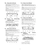
7.12. Remove the SU-Board
1. Remove the flexible cables (SU1B, SU2B, SU3B, SU4B
and SU5B).
2. Disconnect the flexible cable (SU11-SD11) and discon-
nect bridge connector (SU41-SC41).
3. Remove the screws (
×
3 ,
×
3
) and remove the SU-
Board.
7.13. Remove the SD-Board
1. Disconnect the flexible cables (SD1B, SD2B, SD3B,
SD4B and SD5B).
2. Disconnect the flexible cable (SD11-SU11) and discon-
nect bridge connectors (SD42-SC42 and SD46-SC46).
3. Remove the screws (
×
3 ,
×
3
) and remove the SD-
Board.
7.14. Remove the SC-Board
1. Remove the SU-Board and SD-Board. (See section 7.12.
and 7.13.)
2. Disconnect the connectors (SC2 and SC20).
3. Remove the screws (
×
8
) and remove the SC-Board.
7.15. Remove the SS2-Board
1. Unlock the cable clampers to free the cable.
2. Disconnect the connector (SS32) and disconnect the flex-
ible cables (SS51 and SS52).
3. Disconnect the bridge connector (SS02-SS21).
4. Remove the screws (
×
5
) and remove the SS2-Board.
Содержание Viera TH-65PY800P
Страница 6: ...6 3 2 Applicable signals ...
Страница 16: ...16 6 4 No Picture ...
Страница 32: ...32 8 1 4 Adjustment Volume Location 8 1 5 Test Point Location ...
Страница 40: ...40 ...
Страница 42: ...42 10 3 Wiring 2 ...
Страница 43: ...43 10 4 Wiring 3 ...
Страница 44: ...44 ...
Страница 45: ...45 11 Schematic Diagram 11 1 Schematic Diagram Note ...
Страница 132: ...132 13 1 2 Fan and Flat cable location ...
Страница 133: ...133 13 1 3 Packing ...
Страница 134: ...134 13 1 4 Mechanical Replacement Parts List ...
Страница 139: ...139 13 2 Electrical Replacement Parts List 13 2 1 Replacement Parts List Notes ...


