background image

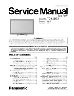
TC-L32E3

9

5 Service Mode

5.1.

How to enter into Service Mode

While pressing [VOLUME ( - )] button of the main unit, press [INFO] button of the remote control three times within 2 seconds.

5.1.1.

Contents of adjustment mode

• Value is shown as a hexadecimal number.
• Preset value differs depending on models.
• After entering the adjustment mode, take note of the value in each item before starting adjustment.

5.1.2.

How to exit

Switch off the power with the [POWER] button on the main unit or the [POWER] button on the remote control.

Main item

Sub item

Sample Data

ADJUST

CONTRAST

000

COLOR

59

TINT

FE

SUB-BRT

800

BACKLGT

20D

B-Y-G

40

R-Y-A

0

VCOM

189

WB-ADJ

R-GAIN

75

G-GAIN

80

B-GAIN

65

R-CENT

80

G-CENT

80

B-CENT

9B

OPTION

Boot

ROM

STBY-SET

00

EMERGENCY

ON

CLK MODE

00

CLOCK

FC7

EDID-CLK

HIGH

SRV-TOOL

00

Содержание VIERA TC-L32E3

Страница 1: ...cifications 8 5 Service Mode 9 5 1 How to enter into Service Mode 9 5 1 1 Contents of adjustment mode 9 5 1 2 How to exit 9 5 2 SRV TOOL 10 5 2 1 How to access 10 5 2 2 Display of SOS History 10 5 2 3 POWER ON TIME COUNT 10 5 2 4 Exit 10 5 2 5 Self Check Mode 11 5 2 6 Hotel Mode Adjustment 11 5 2 7 Hotel Mode 11 6 Troubleshooting Guide 12 6 1 Check of the IIC bus lines 12 6 1 1 How to access 12 6 ...

Страница 2: ...Schematic Diagram 36 11 7 A Board 6 17 Schematic Diagram 37 11 8 A Board 7 17 Schematic Diagram 38 11 9 A Board 8 17 Schematic Diagram 39 11 10 A Board 9 17 Schematic Diagram 40 11 11 A Board 10 17 Schematic Diagram 41 11 12 A Board 11 17 Schematic Diagram 42 11 13 A Board 12 17 Schematic Diagram 43 11 14 A Board 13 17 Schematic Diagram 44 11 15 A Board 14 17 Schematic Diagram 45 11 16 A Board 15 ...

Страница 3: ...between the jumpered AC plug and each exposed metallic cabinet part on the equipment such as screwheads connectors control shafts etc When the exposed metallic part has a return path to the chassis the reading should be 100 Mohm and over When the exposed metal does not have a return path to the chassis the reading must be 1 1 2 Leakage Current Hot Check See Figure 1 1 Plug the AC cord directly int...

Страница 4: ...osure of the assembly 3 Use only a grounded tip soldering iron to solder or unsolder ES devices 4 Use only an anti static solder removal device Some solder removal devices not classified as anti static ESD protected can generate electrical charge sufficient to damage ES devices 5 Do not use freon propelled chemicals These can generate electrical charges sufficient to damage ES devices 6 Do not rem...

Страница 5: ...ctured using lead free solder will have the PbF within a leaf Symbol PbF stamped on the back of PCB Caution Pb free solder has a higher melting point than standard solder Typically the melting point is 50 70 F 30 40 C higher Please use a high temperature soldering iron and set it to 700 20 F 370 10 C Pb free solder will tend to splash when heated too high about 1100 F or 600 C If you must use Pb s...

Страница 6: ...nction A BOARD Digital Signal Processor Tuner Speaker out AV Terminal HDMI in SD Card PC in KA BOARD Remote Receiver LED K BOARD Power button Control panel button and control panel bracket together P BOARD Power Supply TC BOARD T CON LD BOARD LED Driver Back Light ...

Страница 7: ...l frequency kHz vertical frequency Hz COMPONENT HDMI PC 525 480 60i 15 73 59 94 525 480 60p 31 47 59 94 750 720 60p 45 00 59 94 1 125 1 080 60i 33 75 59 94 1 125 1 080 60p 67 43 59 94 1 125 1 080 60p 67 50 60 00 1 125 1 080 24p 26 97 23 98 1 125 1 080 24p 27 00 24 00 640 400 70 31 47 70 08 640 480 60 31 47 59 94 Macintosh13 640 480 35 00 66 67 640 480 75 37 50 75 00 852 480 60 31 44 59 89 800 600 ...

Страница 8: ...lity ATSC NTSC Digital Analog VHF UHF 2 69 CATV 1 135 Operating Conditions Temperature 32 F 95 F 0 C 35 C Humidity 20 80 RH non condensing Connection Terminals VIDEO IN VIDEO RCA PIN Type 1 1 0V p p 75 Ω AUDIO L R RCA PIN Type 2 0 5V rms COMPONENT IN Y 1 0 V p p including synchronization PB PR 0 35 V p p AUDIO L R RCA PIN Type 20 5 V rms HDMI 1 4 TYPE A Connectors 4 This TV supports HDAVI Control ...

Страница 9: ...After entering the adjustment mode take note of the value in each item before starting adjustment 5 1 2 How to exit Switch off the power with the POWER button on the main unit or the POWER button on the remote control Main item Sub item Sample Data ADJUST CONTRAST 000 COLOR 59 TINT FE SUB BRT 800 BACKLGT 20D B Y G 40 R Y A 0 VCOM 189 WB ADJ R GAIN 75 G GAIN 80 B GAIN 65 R CENT 80 G CENT 80 B CENT ...

Страница 10: ...after shipment This indication except 2nd and 1st occurrence after shipment will be cleared by Self check indication and forced to factory shipment setting 5 2 3 POWER ON TIME COUNT Note To display TIME COUNT menu highlight position then press MUTE for 3sec Time Cumulative power on time indicated hour minute by decimal Count Number of ON times by decimal Note This indication will not be cleared by...

Страница 11: ... 4 Explain the Hotel mode setup menu Item Function Mode Select hotel mode ON OFF Input Select input signal modes Set the input when each time power is switched on Selection RF HDMI1 HDMI2 HDMI3 Component Video PC Off give priority to a last memory Channel Select channel when input signal is RF Set the channel each time power is switched on Selection Any channel number or means the channel when tur...

Страница 12: ...y Produce TV reception screen and while pressing VOLUME button on the main unit press OK button on the remote control for more than 3 seconds Self check indication and forced to factory shipment setting Produce TV reception screen and while pressing VOLUME button on the main unit press MENU button on the remote control for more than 3 seconds 6 1 2 Exit Disconnect the AC cord from wall outlet 6 1 ...

Страница 13: ...he unit as follow 6 3 No Power First check point There are following 2 states of No Power indication by power LED 1 No lit 2 Red is lit then turns red blinking a few seconds later See 6 2 LCD Remark EEPROM ADR address PCB NAME Times SOS 1 BackLight_SOS 0 0461 TNPH0906 0907 2 FAN_SOS Peaks 0 045C 3 SOS Tuner_SOS SUB3 3V panel_15V 0 045B 4 SUB12V_SENSE_SOS 0 045A 7 SUB3 3V_SENSE_SOS 0 0459 9 SOUND_S...

Страница 14: ...TC L32E3 14 7 Disassembly and Assembly Instructions 7 1 AC Cord Dressing 1 Fix Re Use band at bottom bracket 2 Cover AC cord with protect sheet and dressing with re use band follow sequence 1 2 3 4 ...

Страница 15: ...TC L32E3 15 7 2 Control Panel Assembly Side AV Installation 1 Fix control panel button into control panel bracket 2 Stick felt TMK4GA144 on control panel bracket ...

Страница 16: ...TC L32E3 16 7 3 Speaker and Bottom Bracket Installation 1 Fix SP RUBBER BUSH at SP UNIT L R 2 Install SP UNIT L and SP UNIT R 3 Install Bottom Bracket ...

Страница 17: ... may cause scratches on the surface 3 Take care not to subject the TV s surface to water or detergent Any liquid including pets urine if enters the product could lead to TV failure 4 Take care not to subject the surface to insect repellent solvent thiner or other voiltile substances This may degrade surface quality or cause peeling of the paint 5 The surface of the display panel is specially treat...

Страница 18: ...TC L32E3 18 7 5 LED Panel and Bracket Assembly 1 Fixing LED panel at cabinet and fix screw 2 Stick clamper at cabinet Fixing Metal bracket P bracket and Vesa bracket ...

Страница 19: ...TC L32E3 19 7 6 Install and Screw PCB 1 Install P print on LCD panel 2 Install A print on LCD panel 3 Install Metal Bracket PCB A on LCD panel ...

Страница 20: ...TC L32E3 20 7 7 Disassembly P board A board and LD board 1 Open the control panel and side av bracket 2 Open 6 pcs screw at P Board 3 Open 6 pcs screw at A Board 4 Open 4 pcs screw at LD Board ...

Страница 21: ...ntrol Panel 2 Install side AV bracket 3 Install Speaker Bracket 4 4 Install Metal Bracket Bottom 5 Screw Control Panel into board 6 Screw Side Av Bracket 7 Screw Metal Bracket Bottom 8 Screw Speaker bracket 9 Slot clamper into LCD Panel 10 Slot LVDS wire and Stick PetAl tape ...

Страница 22: ...TC L32E3 22 7 9 Back Cover Screw 1 Screw back cover 2 Stick model name plate rear av indication sheet at back cover 3 Stick serial no label at back cover ...

Страница 23: ...TC L32E3 23 7 10 Disassembly Back Cover Screw Open Screw back cover ...

Страница 24: ...TC L32E3 24 7 11 Pedestal Assembly 1 Stick a rubber foots for pedestal base plate 2 Fix a pedestal base plate and pedestal stand metal screw need 3 Fix a pedestal cover screw need ...

Страница 25: ...TC L32E3 25 7 12 Stand Mounting Assembly ...

Страница 26: ...F PFC390V TP7201 7202 390 15 Reception HOT TP7203 7204 HOT LED24V TP7514 7515 24 2 Reception DTV16V TP7503 7504 16 1 5 Reception STBY6V TP7501 7502 5 8 0 8 Reception 5 8 0 8 Stand by Instrument Name Remarks 1 REMOTE TRANSMITTER 2 Ex Signal Sprit color bar Adjustment or Inspection Procedure Remarks procedure 1 Receive the Sprit color bar Screen mode ZOOM or FULL Picture mode DYNAMIC AI OFF AI Pictu...

Страница 27: ...ENSOR TMDS DATA SUB_ON VON31V 5 8VS NAND FLASH VIDEO_OUT STB5V CH SUB1 5V KEY3 A10 DCDC HDMI2 HDMI3 COMP ETHERNET PANEL SUB1 5V TMDS DATA REMOTE RECEIVER BL_ON 5 8VS USB DATA PFC CIRCUIT TMDS DATA 24V POWER EEPROM CPU BUS I F POWER LED BL_SOS SUB1 2V TU HDMI3 3V EEPROM KEY1 MENU KEY3 T CON DCDC RECTIFIER LIVE P15V F16V KA DDR3 KEY1 VOL TUNER C A T S SENSOR SUB3 3V LCD PANEL OUT P4 LED DRIVER PWM S...

Страница 28: ...CORD 5 BL_ON MENU 24V 9 TC2 9 PWM DCDCEN P1 10 49 T7201 5 14 Y 10 48 11 Q9503 L R COMP 3 PC B 7 63 IC9500 TV 6 16 14 RELAY 56 SOS SUB5V VIDEO JK3703 Q2002 LD2 45 PB L R LF7101 8 LD4 INPUT OK LED4 RECTIFIER L ANODE2 IIC0 OUT R LED7 PR IC7301 STB V CF7102 10 L R JK3000A TCON DCDC SCL VON31V Q4151 52 58 6V GENE 20 LEVEL SHIFT VOFF2 6V SOS Q4150 SDA IC4150 IIC0 2 5V OVP PC G 12 6V COMPARATOR SOS_SENCE...

Страница 29: ...DMI_5V_DET3 PEAKS EEPROM REMOTE RECEIVER IC4700 D3050 1 8V IIC1 ETHERNET SUB3 3V DDC IIC0 DDC1_IIC STB3 3V IIC1 1 2V IIC3 IF_AGC IIC3 DDC3_IIC DDC2 PANEL_VCC_ON SUB3 3V IC5601 DCDCEN TCON_SOS BL ON RX2 KEY3 SIF SIF IC8902 DDR3 USB1VBUS IC5602 IFD DMD_ IIC0 JK1000 SD CARD OVP Rx1 TMDS DATA CLOCK STB_RST IC8201 KEY3 DDC1 SW_OFF_DET 5 R_LED_ON DDC0 HDMI MUX DMD_ IIC0 Rx2 JK1002 Rx0 IF_AGC HDMI_CEC HD...

Страница 30: ...TC L32E3 30 10 Wiring Connection Diagram 10 1 Wire Dressing Wire Clamper 1 2 3 4 5 6 7 8 9 10 No 1 A09 P2 No 2 Panel LD print No 3 P4 LD4 No 4 A10 KA10 No 5 A11 SP L No 6 A11 SP R ...

Страница 31: ...TC L32E3 31 11 Schematic Diagram 11 1 Schematic Diagram Notes ...

Страница 32: ...TC L32E3 32 11 2 A Board 1 17 Schematic Diagram 6 5 4 3 2 1 A B C D E F G H I ...

Страница 33: ...TC L32E3 33 11 3 A Board 2 17 Schematic Diagram 6 5 4 3 2 1 A B C D E F G H I ...

Страница 34: ...TC L32E3 34 11 4 A Board 3 17 Schematic Diagram 6 5 4 3 2 1 A B C D E F G H I ...

Страница 35: ...TC L32E3 35 11 5 A Board 4 17 Schematic Diagram 6 5 4 3 2 1 A B C D E F G H I ...

Страница 36: ...TC L32E3 36 11 6 A Board 5 17 Schematic Diagram 6 5 4 3 2 1 A B C D E F G H I ...

Страница 37: ...TC L32E3 37 11 7 A Board 6 17 Schematic Diagram 6 5 4 3 2 1 A B C D E F G H I ...

Страница 38: ...TC L32E3 38 11 8 A Board 7 17 Schematic Diagram 6 5 4 3 2 1 A B C D E F G H I ...

Страница 39: ...TC L32E3 39 11 9 A Board 8 17 Schematic Diagram 6 5 4 3 2 1 A B C D E F G H I ...

Страница 40: ...TC L32E3 40 11 10 A Board 9 17 Schematic Diagram 6 5 4 3 2 1 A B C D E F G H I ...

Страница 41: ...TC L32E3 41 11 11 A Board 10 17 Schematic Diagram 6 5 4 3 2 1 A B C D E F G H I ...

Страница 42: ...TC L32E3 42 11 12 A Board 11 17 Schematic Diagram 6 5 4 3 2 1 A B C D E F G H I ...

Страница 43: ...TC L32E3 43 11 13 A Board 12 17 Schematic Diagram 6 5 4 3 2 1 A B C D E F G H I ...

Страница 44: ...TC L32E3 44 11 14 A Board 13 17 Schematic Diagram 6 5 4 3 2 1 A B C D E F G H I ...

Страница 45: ...TC L32E3 45 11 15 A Board 14 17 Schematic Diagram 6 5 4 3 2 1 A B C D E F G H I ...

Страница 46: ...TC L32E3 46 11 16 A Board 15 17 Schematic Diagram 6 5 4 3 2 1 A B C D E F G H I ...

Страница 47: ...TC L32E3 47 11 17 A Board 16 17 Schematic Diagram 6 5 4 3 2 1 A B C D E F G H I ...

Страница 48: ...TC L32E3 48 11 18 A Board 17 17 Schematic Diagram 6 5 4 3 2 1 A B C D E F G H I ...

Страница 49: ...TC L32E3 49 11 19 KA Board Schematic Diagram 6 5 4 3 2 1 A B C D E F G H I ...

Страница 50: ...TC L32E3 50 11 20 LD Board Schematic Diagram 6 5 4 3 2 1 A B C D E F G H I ...

Страница 51: ...TC L32E3 51 11 21 P Board Schematic Diagram 6 5 4 3 2 1 A B C D E F G H I ...

Страница 52: ...TC L32E3 52 11 22 TC Board Schematic Diagram 6 5 4 3 2 1 A B C D E F G H I ...

Страница 53: ...824 R0945 C3108 R3101 C3933 C8627 R4182 R4723 R4130 R4123 C4913 C2003 FL4007 VJ4708 C4819 C4814 R0952 C4017 C8126 D3108 L8601 L5604 L4810 D4733 D4728 CN0100 C6869 IC8201 B C6855 R4068 R5002 R4806 R4601 R8670 VJ8924 C5621 TD9902 R2790 A15 D4171 D4748 R4154 C6881 R6851 IC4900 D4712 VJ4800 C2012 Q4514 R8858 R8660 C3118 D2763 R2794 R4985 R0909 R4784 L4809 D4714 FL3102 R4810 R4000 R8625 R8612 C8620 C68...

Страница 54: ...153 R4146 R3196 C4135 R3353 TD6850 R8901 C2775 C8902 IC5601 TP4902 TP4502 C1951 R4028 C8200 TP4022 R4921 TP4007 C4129 TP0906 CN8958 L8016 R2751 C8711 R5023 TP2002 TP4701 R5007 D1954 R4009 R5175 VJ1000 C8223 R4167 R4111 Q4512 TP8600 C0083 R8905 IC8700 R8305 ZA068 R1961 C8108 R8853 R4007 R0942 C4002 D0913 R0902 TP4062 R8200 C5151 TP4042 Q2002 TP8602 Q1951 C3081 R8438 R0922 TP4064 TP4057 R4767 TP4043...

Страница 55: ... TP2804 TP2806 TP2807 TP2808 TP2809 KA K A 1 0 RM2800 AB AD A E A F AA AC A G TNPA5378 1 3 KA 1 Q 2 8 0 0 Q 2 8 0 2 Q 2 8 0 1 1 S U F F I X 1 7 SN2800 KA10 C2801 C2802 C2803 Q2800 C2804 Q2801 C2805 Q2802 C2806 C2807 C2809 C2811 D2800 D2801 D2802 D2803 R2800 D2804 R2801 D2805 R2802 R2803 R2804 R2805 R2806 R2807 R2808 R2809 R2810 R2811 R2815 R2817 R2825 R2826 R2827 R2828 R2829 R2830 R2831 D2800A D28...

Страница 56: ... L9500 L9501 L9502 LD2 L9503 LD4 C9501 C9502 C9503 C9504 Q9500 C9505 Q9501 C9506 Q9502 C9507 Q9503 C9508 Q9504 C9509 Q9505 Q9506 4 1 5 9 C 3 1 5 9 C 2 1 5 9 C 1 1 5 9 C 0 1 5 9 C C9515 C9516 C9518 C9520 C9521 C9522 C9523 C9524 D9500 C9525 D9501 C9526 D9502 C9527 D9503 C9528 D9504 R9500 D9505 R9501 D9506 R9502 D9507 R9503 D9508 R9504 D9509 R9505 R9506 R9507 R9508 IC9500 R9509 D9510 R9701 R9702 R970...

Страница 57: ...1 4 T P 9 5 1 5 T P 9 5 1 6 T P 9 5 1 7 T P 9 5 1 8 T P 9 5 1 9 TP9520 TP9521 TP9522 T P 9 5 2 3 TP9524 TNPA5377 1 LD T P 9 5 2 6 T P 9 5 2 7 T P 9 5 2 5 TP9529 TP9528 C9517 C9500 R E V E R S E F O R S U F F I X S E E C9500 C9517 TP9500 TP9501 TP9502 TP9503 TP9504 TP9505 TP9506 TP9507 TP9508 TP9509 TP9510 TP9511 TP9512 TP9513 TP9514 TP9515 TP9516 TP9517 TP9518 TP9519 TP9520 TP9521 TP9522 TP9523 TP...

Страница 58: ... I J H G F E D C B A 1 2 3 4 5 6 P BOARD TOP COMPONENT SIDE TNPA5364 P Parts Location IC7301 Ref No Location Ref No Location E4 D7102 D7103 D7203 D7204 D7205 D7302 D7303 D7332 D7333 D7501 D7502 B4 B4 B3 B4 C3 B4 B4 E4 E4 F1 E1 ...

Страница 59: ...102 D7103 D7201 D7202 D7203 D7204 D7205 D7207 D7208 D7209 D7211 D7302 D7303 D7313 E1 E4 E4 D4 D4 E3 E3 D3 C2 C2 E3 D3 F4 E4 A3 D7326 D7327 D7328 D7329 D7330 D7331 D7332 D7333 D7334 D7335 D7336 D7337 D7338 D7339 B4 B3 B4 B4 B3 B4 B4 B4 A3 B4 B4 B4 B4 B4 D7325 B6 D7340 B4 D7339 B4 D7603 D2 D7341 D7342 D7343 D7402 D7403 D7404 D7501 D7502 D7506 D7507 D7508 D7600 D7601 D7602 B4 B4 B4 D5 F5 E5 A1 B1 E1 ...

Страница 60: ...ARD BOTTOM COMPONENT SIDE TNPA5391 TC TC1 TC2 TC3 TNPA5391 1 TC A G AC AA A F A E AD AB 1 60 1 60 1 8 0 S U F F I X TC1 TC2 TC3 C9101 C9102 C9103 C9104 C9105 C9106 C9107 C9108 C9109 C9110 C9111 C9112 C9113 C9114 R9101 R9102 R9103 R9104 R9105 R9106 R9107 R9108 R9109 R9110 R9111 R9112 R9113 R9114 R9115 ...

Страница 61: ...and Replacement Parts List 13 1 Exploded View and Mechanical Replacement Parts List Please click the radio button for Diagrams ll Parts List on the menu bar 13 2 Electrical Replacement Parts List 13 2 1 Replacement Parts List Notes ...

Страница 62: ...1UF 16V C4130 F1G1C104A077 C 0 1UF 16V C4131 F1G1C104A077 C 0 1UF 16V C4132 F1G1C104A077 C 0 1UF 16V C4133 F1G1C104A077 C 0 1UF 16V C4134 F1H1C105A145 C 0 1UF 50V C4135 F1H1H104A970 C 0 1UF 16V C4137 F1K1C106A126 C 0 1UF 16V C4138 F1H1H104A970 C 0 1UF 16V C4139 F1H1H104A970 C 0 1UF 16V C4140 F1G1H101A565 C 100PF 50V C4149 F1H1C105A145 C 0 1UF 50V C4150 F1J1E475A251 C 4 7UF 25V C4151 F1G1C104A077 C...

Страница 63: ...8 F1J1H103A834 C 0 01UF 50V C7219 F1J1H2240009 C 0 22UF 50V Safety Ref No Part No Part Name Description Remarks C7220 F1A3A471A060 C 470PF 1kV C7221 F1J1H102A721 C 1000PF 50V C7301 F2A2W8200011 C 82UF 450V C7302 F1J1H102A721 C 1000PF 50V C7314 F0C2K273A046 C 0 027UF 800V C7320 F1J1E223A226 C 0 022UF 25V C7321 F1J1H221A709 C 220PF 50V C7322 F2A1V4710023 C 470UF 35V C7323 F1J1H104A717 C 0 1UF 50V C7...

Страница 64: ...4A077 C 0 1UF 16V C8717 F1G1C104A077 C 0 1UF 16V C8721 F1K1E106A136 C 10UF 25V C8722 F1K1E106A136 C 10UF 25V C8723 F1K1E106A136 C 10UF 25V C8724 F1K1E106A136 C 10UF 25V C8764 F1H1A105A025 C 1UF 10V Safety Ref No Part No Part Name Description Remarks C8765 F1H1A105A025 C 1UF 10V C8769 F1G1C223A081 C 0 022UF 16V C8772 F1J1A106A043 C 10UF 10V C8773 F1J1A106A043 C 10UF 10V C8900 F1G1C104A077 C 0 1UF 1...

Страница 65: ...IC9500 C0ZBZ0001816 IC COILS L2001 J0JYC0000065 COIL L2310 J0JHC0000078 BEAD CORE L2311 J0JHC0000078 BEAD CORE L2312 J0JHC0000078 BEAD CORE L2313 J0JHC0000078 BEAD CORE L2750 J0JYC0000065 COIL L2751 J0JYC0000065 COIL L2754 J0JYC0000065 COIL L3000 J0JCC0000287 COIL L3001 J0JCC0000287 COIL L3002 J0JCC0000287 COIL L3006 G1C100MA0072 COIL L3122 J0JCC0000287 COIL L3123 J0JCC0000287 COIL L4000 J0JHC0000...

Страница 66: ...3 C 68OHM J 1 16W R0936 D0GA680JA023 C 68OHM J 1 16W R0937 D0GA680JA023 C 68OHM J 1 16W R0938 D0GA680JA023 C 68OHM J 1 16W R0939 D0GA680JA023 C 68OHM J 1 16W R0940 D0GA680JA023 C 68OHM J 1 16W R0941 D0GA680JA023 C 68OHM J 1 16W R0942 D0GA680JA023 C 68OHM J 1 16W R0943 D0GA680JA023 C 68OHM J 1 16W R0944 D0GA101JA023 C 100OHM J 1 16W R0945 D0GA102JA023 C 1KOHM J 1 16W R0947 D0GA680JA023 C 68OHM J 1 ...

Страница 67: ...16W Safety Ref No Part No Part Name Description Remarks R4166 D0GA223JA023 C 22KOHM J 1 16W R4167 D0GA473JA023 C 47KOHM J 1 16W R4168 D0GA103JA023 C 10KOHM J 1 16W R4169 D0GA103JA023 C 10KOHM J 1 16W R4170 D0GA103JA023 C 10KOHM J 1 16W R4171 D1BA3002A023 C 30KOHM J 1 16W R4172 D1BA1203A023 C 120KOHM J 1 16W R4173 D0GA103JA023 C 10KOHM J 1 16W R4178 D1BA2202A023 C 22KOHM J 1 16W R4181 D1BA1002A014 ...

Страница 68: ...J 1 8W R7362 D0GD821JA052 C 820OHM J 1 8W Safety Ref No Part No Part Name Description Remarks R7364 D0GD103JA052 C 10KOHM J 1 8W R7365 D0GD103JA052 C 10KOHM J 1 8W R7367 D0GD152JA052 C 1 5KOHM J 1 8W R7376 D0GD223JA052 C 22KOHM J 1 8W R7377 D0GD103JA052 C 10KOHM J 1 8W R7380 ERX1SJR22 0 22OHM J 1W R7381 ERX1SJR22 0 22OHM J 1W R7387 D0GD152JA052 C 1 5KOHM J 1 8W R7388 D0GD162JA052 C 1 6KOHM J 1 8W ...

Страница 69: ...6W R8917 EXB2HV680JV 68OHM J 1 16W R8918 D0GA680JA023 C 68OHM J 1 16W R8919 D0GA680JA023 C 68OHM J 1 16W R8920 EXB28V680JX 68OHM J 1 10W R8921 EXB28V680JX 68OHM J 1 10W Safety Ref No Part No Part Name Description Remarks R8922 D0GA680JA023 C 68OHM J 1 16W R8923 D0GA680JA023 C 68OHM J 1 16W R8924 EXB28V680JX 68OHM J 1 10W R8925 EXB28V680JX 68OHM J 1 10W R8965 EXB28V103JX 10KOHM J 1 16W R9006 D0GAR0...

Страница 70: ...AA0000363 PHOTO COUPLER PC7303 B3PAA0000363 PHOTO COUPLER RM2800 PNJ4815M01TV REMOCON SENSOR SN2800 B3JB00000078 PHOTO DETECTOR SW7402 EVQ11G05R SWITCH SW7403 EVQ11G05R SWITCH SW7404 EVQ11G05R SWITCH SW7405 EVQ11G05R SWITCH SW7406 EVQ11G05R SWITCH SW7407 EVQ11G05R SWITCH SW7410 EVQ11G05R SWITCH TC1 K1MY60B00005 CONNECTOR TC2 K1MY60B00005 CONNECTOR TC3 K1MN80BA0296 CONNECTOR TU4800B ENGS6302D5F TUN...

Страница 71: ...Model No TC L32E3 Parts Location ...

Страница 72: ...Model No TC L32E3 Packing Exploded View ...

Страница 73: ...ET TKP4GA06601 CONTROL PANEL TKP4GA06901 LED PANEL TKX4GA04901 SP BRACKET TKX4GA05001 SP BRACKET 4 TPC4GA12701A PACKING CASE TPD4GA0200 BOTTOM CUSHION TPD4GA0202 TOP CUSHION TQZ4GB369 FAN BAG ASSY TSXM277 LVDS TSXM278 LVDS 5 TTU4GA0505 BACK COVER ASSY 6 TTY4GA0205 CABINET ASSY 7 VVX32F101G00 LCD PANEL XSS5 16FJK SCREW XTV3 10JFJ SCREW XTW3 10TFJ SCREW XYN3 C8FJ SCREW XYN4 F15FJ SCREW XYN4 F30FJK S...

Отзывы: