37
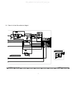
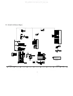
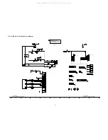
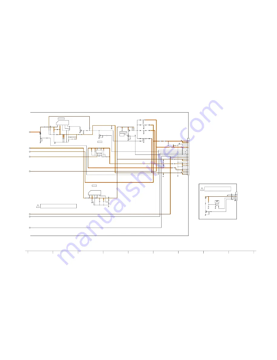
11.3. P-Board (2 of 2) and V-Board Schematic Diagram
+
+
+
+
+
+
+
+
+
+
VCC
GND
OUT
+
C7103
0.22u
16V
C7057
0.01u
50V
C7150
50V
6800p
C7154
0.1u
50V
C7151
50V
0.01u
C7152
0.1u
50V
C7147
50V
0.01u
C7124
0.01u
50V
C7135
10u
10V
C7102
16V
100u
C7148
50V
220u
C7060
220u
25V
C7159
470u
25V
C7149
470u
25V
C7104
50V
33u
C7088
100u
50V
C7160
10u
50V
C7110
25V
470u
C7168
470u
25V
D7045
B0HCMM000014
D7103
MA2J11100L
D7101
MA2J11100L
D7102
MA2J11100L
D7090
B0JCPG000005
D7064
MA2J11100L
D7069
MA2J11100L
D7067
MA2J11100L
D7062
MA2J11100L
D7091
B0HCMM000014
D7066
MA2J11100L
D7058
B0HCMM000014
D7077
B0ACCE000005
D7095
B0BA01400009
D7096
B0BA01400009
D7097
B0BA01400009
C0DBEHE00005
IC7109
1
Vadj
2
GND
3
Vc
5
Vo
4
Vin
C0DAAZG00014
IC7112
1
Vin
2
V
out
3
COM
4
Oadj
5
ON/OFF
C0DAEYH00002
IC7105
1
Vc
2
VIN
3
GND
4
V
OUT
5
ADJ
P3
1
2
3
4
5
6
7
8
9
10
11
12
13
14
15
16
17
18
19
20
21
22
23
L7039
100u
L7026
68u
L7041
10u
TP7051
TP7070
TP7056
TP7055
TP7061
TP7059
TP7071
TP7072
TP7058
TP7057
TP7052
TP7053
TP7054
TP7022
TP7050
TP7015
Q7009
2SD0601ASL
Q7058
2SD0601ASL
Q7022
2SB0709A0L
JS7074
JS7062
JS7075
JS7066
JS7067
JS7068
JS7069
JS7013
R7120
22k
R7112
22k
R7135
10k
R7069
37.4k
1%
R7070
10k
1%
R7061
47k
1%
R7127
37.4k
R7139
0
R7138
15k
1%
R7126
7.15k
R7152
470
1/2W
R7103
47k
R7121
33k
R7111
63.4k
1%
1%
R7156
8.66k
1%
R7155
1k
R7110
10k 1%
R7062
10k
R7122
22k
R7117
47k
R7115
12k
R7157
0
R7102
1k
R7114
0
R7105
2.2k
R7137
22k
R7104
47k
R7123
47k
RM1001
PNA4701M07TV
1
2
3
TP1004
C1006
6.3V
47u
1%
R1022
604
R1028
47
TP1002
D1001
LN1271RALTR
V1
1
2
3
4
Q1006
2SD0601A0L
C1007
0.01u
50V
R1008
22k
TP1003
R1029
1k
TP1001
R1010
22k
<
<
<
<
<
H:SOS
L:NORM
SHORT SOS
TV_SOS
TV_SUB_ON
24V_DET
TV_MAIN_ON
BT_30V
PANEL_12V
PANEL_12V
DTV12V
SUB_9V
SUB_9V
GND
SUB_5V
SOUND_VCC
OVP_DET
SOUND_VCC
5VS
SUB9V
PANEL_ON
DTV12V
GND
GND
GND
GND
PANEL12V
SUB5V
SUB_5V
TO
A-BOARD
(A3)
P-BOARD TXN/P10NGCS (2/2)
!
10
16
18
15
12
17
11
14
13
REMOCON SENSOR
POWER LED
V-BOARD TNPA4483S
!
STB 3.3
REMOTE
GND
R_LED_ON
TO
A-BOARD
(A1)
8
6
7
4
5
3
2
1
TC-32/26LX85
P-Board (2/2) and V-Board Schematic Diagram
TC-32/26LX85
P-Board (2/2) and V-Board Schematic Diagram
All manuals and user guides at all-guides.com
Содержание Viera TC-26LX85
Страница 17: ...17 7 12 EMI processing 32 inch All manuals and user guides at all guides com ...
Страница 18: ...18 All manuals and user guides at all guides com ...
Страница 19: ...19 All manuals and user guides at all guides com ...
Страница 20: ...20 All manuals and user guides at all guides com ...
Страница 21: ...21 7 13 EMI processing 26 inch All manuals and user guides at all guides com a l l g u i d e s c o m ...
Страница 22: ...22 All manuals and user guides at all guides com ...
Страница 23: ...23 All manuals and user guides at all guides com ...
Страница 26: ...26 All manuals and user guides at all guides com a l l g u i d e s c o m ...
Страница 30: ...30 All manuals and user guides at all guides com ...
Страница 32: ...32 10 2 Wiring 32 inch All manuals and user guides at all guides com ...
Страница 33: ...33 10 3 Wiring 26 inch All manuals and user guides at all guides com ...
Страница 34: ...34 All manuals and user guides at all guides com ...
Страница 35: ...35 11 Schematic Diagram 11 1 Schematic Diagram Notes All manuals and user guides at all guides com ...
Страница 50: ...50 All manuals and user guides at all guides com ...
Страница 52: ...52 13 1 2 Mechanical Replacement Parts List All manuals and user guides at all guides com ...

