background image

11.2. INTERCONNECTION SCHEMATIC DIAGRAM

LENS UNIT

SPEAKER UNIT

SPEAKER

2

1

SP-
SP+

P51

USB

BATTERY

AV

LITHIUM

MAIN P.C.B.

EVF BACKLIGHT P.C.B.

FRONT P.C.B.

REAR CASE UNIT

CATCHER

BATTERY

MONITOR LCD PANEL

EVF LCD PANEL

DVD DRIVE UNIT

DISC COVER LOCK UNIT

LCD BACKLIGHT P.C.B.

DOOR OPEN SWITCH

DOOR LOCK SWITCH

DOOR OPEN SW

GND

GND

DOOR LOCK SW

MOTOR+

MOTOR+

MOTOR-

MOTOR-

8

7

6

5

4

3

2

1

P2403

60

59

58

57

56

55

54

53

52

51

50

49

48

47

46

45

44

43

42

41

40

39

38

37

36

35

34

33

32

31

30

29

28

27

26

25

24

23

22

21

20

19

18

17

16

15

DOOR OPEN SW2

DOOR OPEN SW1

RESET

DB7

DB6

DB5

DB4

DB3

DB2

DB1

DB0

GND

DIOW

TOROY

INTRQ

DA1

DA0

5V

5V

5V

DASP

M GND

M GND

UARTI

UARTO

3.3V

3.3V

3.3V

1.2V

1.2V

GND

GND

GND

GND

GND

GND

GND

GND

M GND

LCD CLOSE

REG4.75

REG4.75

REG4.75

DA2

DS3FX

DS1FX

DMACK

DB15

DIOR

DB13

DB11

DB9

GND

GND

DMARQ

DB14

DB12

DB10

DB8

DRV ENG

14

13

12

11

10

9

8

7

6

5

4

3

2

1

B4001

EVF SLIDE
SWITCH

EVF FPC

POWER

CONTROL

SUB SYSCON

TG/AFE

LENS DRIVE

AVIO

VIDEO

MEMORY

JACK

EVF/LCD

TO EVR

LCD
REVERS
SWITCH

LCD
SHAFT FPC

ECM(L)

MIC UNIT

ECM(R)

W

T

ZOOM

O.I.S.

MENU

REC START/STOP

DELET

DISC EJECT

JOYSTICK

MODE DIAL/
POWER

SIDE CASE (L) UNIT

REMOTE
CONTROL
RECEIVER

U6504

NC

FP8902

COM

CKV

STV

ENB

CSV

VBB

DSD

DSG

CSH

VDD

VSS

STH

CKH2

CKH1

B

R

G

MAIN CONNECTION

8

9

10

7

6

L

M

N

K

J

5

4

3

2

1

I

H

INTERCONNECTION SCHEMATIC DIAGRAM

VDR-D50,D51,D58

VDR-D50P

38

Содержание VDR-D50E

Страница 1: ...pying and distribution is a violation of law Model No VDR D50P VDR D50PC VDR D50EG VDR D50E VDR D50EB VDR D50EP VDR D50EE VDR D50EF VDR D50GC VDR D50GCS VDR D50GN VDR D50GT VDR D50SG VDR D50PL VDR D51EE VDR D58GK VOL 1 Colour S Silver Type DVD Video Camera ORDER NO VM0712051CE B17 ...

Страница 2: ...s Unit 27 9 Measurements and Adjustments 28 9 1 EEPROM Data for spare parts of the MAIN P C B 28 9 2 Service Positions 28 9 3 Location for Connectors of the Main P C B 30 9 4 Electrical Adjustment Procedures 31 10 Maintenance 34 10 1 Cleaning Lens Viewfinder and LCD Panel 34 10 2 Cleaning Disc 34 10 3 Cleaning optical pickup 34 11 Schematic Diagrams 37 11 1 OVERALL SCHEMATIC DIAGRAM 37 11 2 INTERC...

Страница 3: ... a shock hazard and the equipment should be repaired and rechecked before it is returned to the customer Figure 1 1 Safety Precaution 1 1 General Guidelines 1 IMPORTANT SAFETY NOTICE There are special components used in this equipment which are important for safety These parts are marked by in the Schematic Diagrams Circuit Board Layout Exploded Views and Replacement Parts List It is essential tha...

Страница 4: ...ssembly 3 Use only a grounded tip soldering iron to solder or unsolder ES devices 4 Use only an antistatic solder removal device Some solder removal devices not classified as antistatic ESD protected can generate electrical charge sufficient to damage ES devices 5 Do not use freon propelled chemicals These can generate electrical charges sufficient to damage ES devices 6 Do not remove a replacemen...

Страница 5: ...d Free Solder PbF The lead free solder has to be used when repairing the equipment for which the lead free solder is used Definition The letter of PbF is printed on the PCB using the lead free solder To put lead free solder it should be well molten and mixed with the original lead free solder Remove the remaining lead free solder on the PCB cleanly for soldering of the new IC Since the melting poi...

Страница 6: ...st not be used until a replacement cover is obtained A replacement fuse cover can be purchased from your local Panasonic Dealer If the fitted moulded plug is unsuitable for the socket outlet in your home then the fuse should be removed and the plug cut off and disposed of safety There is a danger of severe electrical shock if the cut off plug is inserted into any 13 ampere socket If a new plug is ...

Страница 7: ...t must never be subjected to excessive heat or discharge It must therefore only be fitted in equipment designed specifically for its use Replacement batteries must be of the same type and manufacture They must be fitted in the same manner and location as the original battery with the correct polarity contacts observed Do not attempt to re charge the old battery or re use it for any other purpose I...

Страница 8: ...2 5 How to Recycle the Lithium Battery U S Only 8 VDR D50P ...

Страница 9: ...on AC Adapter used on the following model VDR D58GK However the AC Adapter replacement part number is DE A51DA which should be used when ordering Notes 2 1 This service manual does not contain the following information because of the impossibility of sevicing at component level 1 Schematic Diagram Block Diagram and P C B layout of Main P C B 2 Parts List for individual parts of Main P C B 2 The fo...

Страница 10: ...3 2 Service Caution 3 2 1 Precaution of Laser Light Please remove the AC adapter charger or battery at servicing that opens the Disc Cover 10 VDR D50P ...

Страница 11: ... with normal product the disc cannot be removed while the ACCESS indicator is lit or blinking 3 3 2 Procedure for Removing the disc manually Please removing the disc by the following procedure when the disc cannot be removeing due to the breakdown of the electrical system etc 1 Insert the small Clip or similar object into the Eject hole 2 Press it gently and then open the Disc cover 3 Remove the d...

Страница 12: ...4 Specifications 12 VDR D50P ...

Страница 13: ...5 Location of Controls and Components Followings are the Location of Controls and Components for VDR D50P PC as a sample For other models refer to each Operatin Instructions 13 VDR D50P ...

Страница 14: ...14 VDR D50P ...

Страница 15: ...6 Service Mode 6 1 Error Display PUSH THE RESET SWITCH is displayed automatically on the EVF or the LCD Monitor when an undesirable condition has occured 15 VDR D50P ...

Страница 16: ...E button JOYSTICK CONTROL LEFT button and RECORDING START STOP button simmultaneously for 3 seconds 3 To select the Item 1 Press the JOYSTICK CONTROL UP DOWN to select item 1 or 4 2 Press the JOYSTICK CONTROL RIGHT to display YES NO screen 3 Press the JOYSTICK CONTROL UP DOWN to select YES 4 Press the JOYSTICK CONTROL CENTER 4 To exit the Service Menu 1 Unplug the AC Cord Fig S1 NOTE Do not operat...

Страница 17: ...ompletion CLEAR METHOD If the Card and Disc inserted take out it before Service Mode operation Turn on power and set the Mode Dial to DISC RECORDING MODE Pushed DELEATE button JOYSTICK CONTROL RIGHT and RECORDING START STOP button simmultaneously for 3 seconds 17 VDR D50P ...

Страница 18: ...7 Service Fixture Tools 7 1 Service Tools and Equipment 18 VDR D50P ...

Страница 19: ...Instructions 8 1 Disassembly Frow Chart This flow chart indicates the disassembly steps the cabinet parts P C B and Mecha Unit in order to access to be serviced When reinstalling perform the steps in the reverse order 19 VDR D50P ...

Страница 20: ...8 2 P C B Layout Fig F1 20 VDR D50P ...

Страница 21: ...in P C B 5 Rear EVF Unit Fig D13 2 Screws M 3 Screws N Rear EVF Unit 6 DVD Drive Unit Side L Unit Fig D14 1 Connector P2403 1 Screw O DVD Drive Unit Side L Unit 7 Front P C B Fig D15 4 Screws P Front P C B 8 LCD Backlight P C B Fig D16 2 Screws Q 2 Screws R Earth Plate Side Case R Unit LCD Shaft Unit Side R Piece Fig D17 2 Connectors FP8101 FP8102 2 Screws S 1 Screw T LCD Case A LCD Case B Unit Sh...

Страница 22: ...Fig D1 Fig D2 Fig D3 Fig D4 22 VDR D50P ...

Страница 23: ...Fig D5 Fig D6 Fig D7 Fig D8 23 VDR D50P ...

Страница 24: ...Fig D9 Fig D10 Fig D11 Fig D12 24 VDR D50P ...

Страница 25: ...Fig D13 Fig D14 Fig D15 Fig D16 25 VDR D50P ...

Страница 26: ...Fig D17 Fig D18 Fig D19 Fig D20 Fig D21 26 VDR D50P ...

Страница 27: ...e following flowchart describes order or steps for removing the Camera lens unit and certain printed circuit boards in order to make access to the item needing service To reassemble the unit follow the steps in reverse order Fig L1 Fig L2 27 VDR D50P ...

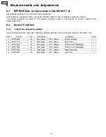
Страница 28: ...nsult the Adjustment Manual which is available in Adjustment software The Adjustment software is available at TSN Website therefore access to TSN Website at Support Information from NWBG VDBG PAVC 9 2 Service Positions 9 2 1 List of the extension cables Use the following extension cables when checking or adjusting individual circuit boards except module Parts Main P C B 28 VDR D50P ...

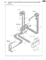
Страница 29: ...9 2 2 Checking and repairing individual circuit boards except module parts Main P C B How to use extension cables 29 VDR D50P ...

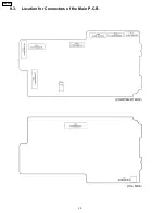
Страница 30: ...9 3 Location for Connectors of the Main P C B 30 VDR D50P ...

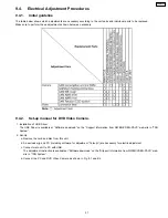
Страница 31: ...e USB Driver is available at Software download on the Support Information from NWBG VDBG PAVC web site in TSN System 2 Set Up a Remove the card and disc from this unit b An exclusive jig and PC including software for adjustment Tatsujin are necessary for electric adjustment c Connect main unit to PC with USB The adjustment instruction is available at Software download on the SUpport Information fr...

Страница 32: ...sary jig mentions it setup electric adjustment Ref Parts Name Parts No Q ty Remarks 1 Personal Computer 1 With Tatsuin Software 2 AC Adaptor 1 The AC Adaptor for Video Camera 3 DC Cable 1 4 USB Cable 1 5 Infinity Lens Fixation Unit 1 6 TATSUJIN PC Adjustment Program 1 32 VDR D50P ...

Страница 33: ...log will appear Click Yes and Save to save the EEPROM data Fig E3 3 6 When EEPROM data has been saved the menu will appear To perform each adjustment display the adjustment menu by selecting from Camera Adjust or Video Adjust and select each adjustment item Fig E3 4 Note The adjusted data is stored in the EEPROM IC after each adjustment 7 After adjustment to close the software select Exit in the F...

Страница 34: ...nd the gently wipe the their surface Note A lens cleaning paper and lens cleaner are available at local camera shops and market place 10 2 Cleaning Disc 10 3 Cleaning optical pickup 1 Attach the AC adapter charger or battery power supply and then slide the DISC EJECT switch to open the disc insertion block 2 Remove the AC adapter charger or battery power supply 3 Check to see whether the optical p...

Страница 35: ...35 VDR D50P ...

Страница 36: ...36 VDR D50P ...

Страница 37: ...IRIS FOCUS LENS DRIVE OIS LENS UNIT USB TERMINAL IC6201 RTC POWER CONTROL IC6004 EEPROM POWER SUPPLY CONTROL CIRCUIT DVD DRIVE UNIT IC1001 POWER SUPPLY IC8001 CONTROLLER SIGNAL PROCESSOR IC3203 FLASH MEMORY IC3202 SDRAM MEMORY LCD BACKLIGHT P C B 0 33 LCD 2 7 WIDE LCD EVF BACKLIGHT P C B IC7801 IC7802 GYRO IC3001 VIDEO SIGNAL PROCESS AUDIO SIGNAL PROCESS MICROCONTROLLER INTERFACE ATAPI INTERFACE S...

Страница 38: ...B3 DB2 DB1 DB0 GND DIOW TOROY INTRQ DA1 DA0 5V 5V 5V DASP M GND M GND UARTI UARTO 3 3V 3 3V 3 3V 1 2V 1 2V GND GND GND GND GND GND GND GND M GND LCD CLOSE REG4 75 REG4 75 REG4 75 DA2 DS3FX DS1FX DMACK DB15 DIOR DB13 DB11 DB9 GND GND DMARQ DB14 DB12 DB10 DB8 DRV ENG 14 13 12 11 10 9 8 7 6 5 4 3 2 1 B4001 EVF SLIDE SWITCH EVF FPC POWER CONTROL SUB SYSCON TG AFE LENS DRIVE AVIO VIDEO MEMORY JACK EVF ...

Страница 39: ... SCHEMATIC DIAGRAM FOR ORDERING WHEN YOU ORDER A PART PLEASE REFER TO PARTS LIST NOTE THE MEASUREMENT MODE OF THE DC VOLTAGE ON THIS DIAGRAM IS STOP MODE NOTE CIRCUIT VOLTAGE AND WAVEFORM DESCRIBED HEREIN SHALL BE REGARDED AS REFERENCE INFORMATION WHEN PROBING DEFECT POINT BECAUSE IT MAY DIFFER FROM AN ACTUAL MEASURING VALUE DUE TO DIFFERENCE OF MEASURING INSTRUMENT AND ITS MEASURING CONDITION AND...

Страница 40: ...OTE CIRCUIT VOLTAGE AND WAVEFORM DESCRIBED HEREIN SHALL BE REGARDED AS REFERENCE INFORMATION WHEN PROBING DEFECT POINT BECAUSE IT MAY DIFFER FROM AN ACTUAL MEASURING VALUE DUE TO DIFFERENCE OF MEASURING INSTRUMENT AND ITS MEASURING CONDITION AND PRODUCT ITSELF LCD BACKLIGHT P C B AMP TO SHAFT FPC FP8101 TO LCD PANEL FP8102 0 0 5 6 0 1 5 1 0 1 1 1 1 1 4 0 3 1 1 1 4 0 3 1 1 1 4 0 3 1 1 1 4 0 3 0 5 0...

Страница 41: ...URING INSTRUMENT AND ITS MEASURING CONDITION AND PRODUCT ITSELF D C 5 4 3 2 1 B A VDR D50 D51 D58 EVF BACKLIGHT SCHEMATIC DIAGRAM TO EVF FPC FP8901 TO LCD PANEL FP8902 11 6 EVF FPC SCHEMATIC DIAGRAM EVF FPC FOR REFERENCE ONLY TO FP8901 TO FP91 TO EVF BACKLIGHT TO MAIN CN VIDEO MAIN SIGNAL PATH EVF SLIDE 5 4 3 2 1 B A VDR D50 D51 D58 EVF FPC SCHEMATIC DIAGRAM 11 7 DISC COVER LOCK UNIT SCHEMATIC DIA...

Страница 42: ...IAGRAM 11 10 CCD SCHEMATIC DIAGRAM AMP VIDEO MAIN SIGNAL PATH CCD FPC FOR REFERENCE ONLY TO FP31 C 5 4 3 2 1 B A VDR D50 D51 D58 CCD FPC SCHEMATIC DIAGRAM TO MAIN CN 11 11 LCD SHAFT FPC SCHEMATIC DIAGRAM LCD SHAFT FPC FOR REFERENCE ONLY TO MAIN CN VIDEO MAIN SIGNAL PATH TO FP81 TO FP8101 LCD REVERS TO LCD BLACKLIGHT C 5 4 3 2 1 B A VDR D50 D51 D58 LCD SHAFT FPC SCHEMATIC DIAGRAM VDR D50P 42 ...

Страница 43: ...12 Printed Circuit Board 12 1 EVF BACKLIGHT P C B FOIL SIDE LSEP8365A1 1 A B C D E 2 3 4 5 6 7 8 9 VDR D50 D51 D58 EVF BLACKLIGHT P C B COMPONENT SIDE VDR D50P 43 ...

Страница 44: ...r P C B THIS CIRCUIT BOARD SHOWS COMPONENT LAYOUT PATTERN FOR COMPONENT SIDE AND FOIL SIDE LAYOUT PATTERNS ARE SINGLE PATTERN FOR EACH SIDE THAT MAKE EASY TO SIGHT THE COMPONENT LAYOUT LSEP8432A1 VDR D50 VDR D58 LSEP8432B1 VDR D51 1 A B C D E 2 3 4 5 6 7 8 9 VDR D50 D51 D58 FRONT P C B VDR D50P 44 ...

Страница 45: ...12 3 LCD BACKLIGHT P C B LSEP8433A1 1 A B C D E 2 3 4 5 6 7 8 9 VDR D50 D51 D58 LCD BLACKLIGHT P C B COMPONENT SIDE FOIL SIDE VDR D50P 45 ...

Страница 46: ...VDR D50P 46 ...

Страница 47: ...13 Parts and Exploded Views 13 1 Exploded Views 13 1 1 Frame Casing Section 47 VDR D50P ...

Страница 48: ...48 VDR D50P ...

Страница 49: ...13 1 2 LCD Section 49 VDR D50P ...

Страница 50: ...13 1 3 Camera Lens Section 50 VDR D50P ...

Страница 51: ...13 1 4 EVF Section 51 VDR D50P ...

Страница 52: ...13 1 5 Packing Parts Accessories Section 52 VDR D50P ...

Страница 53: ...SCREW 1 B26 XQN16 BF4FN SCREW 1 B27 XQN16 BF4FN SCREW 1 B28 XQN16 BF4FN SCREW 1 B29 XQN16 BF4FN SCREW 1 B30 XQN16 BJ5FN SCREW 1 Ref No Part No Part Name Description Pcs Remarks B37 XQN16 BJ5FN SCREW 1 B38 XQN16 BJ5FN SCREW 1 B39 XQN16 BJ5FN SCREW 1 B40 XQN16 BJ5FN SCREW 1 B41 XQN16 BJ5FN SCREW 1 101 LSMA1031 EARTH PLATE SIDE R 1 PSECI 102 LSKM1650 SIDE R PIECE 1 PSECI 103 LSMD0822 LED LIGHT LENS 1...

Страница 54: ...Part No Part Name Description Pcs Remarks 312 LSMD0849 EVF REFLECT PIECE 1 PSECI 313 LSMD0850 EVF SHEET HOLDER 1 PSECI 314 L5BDDXH00027 LCD PANEL 1 PSECI 315 LSEP8365A1 EVF B L P C B 1 PSECI RTL 316 LSKM1648 EYE CAP 1 PSECI 317 LSDL0359 PROTECT PLATE 1 PSECI 318 LSDL0359 PROTECT PLATE 1 PSECI B301 XQN16 BJ4FN SCREW 1 B302 XQN16 BJ4FN SCREW 1 13 2 5 Packing Parts Accessories Section Parts List Ref ...

Страница 55: ...PACITOR CH 6 3V 22U 1 C7804 F3F0J226A055 E CAPACITOR CH 6 3V 22U 1 C8104 ECJ1VC1H390J C CAPACITOR CH 50V 39P 1 C8105 ECJ1VC1H390J C CAPACITOR CH 50V 39P 1 C8106 ECJ1VC1H390J C CAPACITOR CH 50V 39P 1 C8107 ECJ1VB1A105K C CAPACITOR CH 10V 1U 1 C8109 ECJ2FB1A475K C CAPACITOR CH 10V 4 7U 1 C8111 ECJ1XB1C104K C CAPACITOR CH 16V 0 1U 1 C8112 ECJ2FB1A225K C CAPACITOR CH 10V 2 2U 1 C8113 ECJ1VB1A105K C CA...

Страница 56: ... ERA3YED271V M RESISTOR CH 1 16W 270 1 PSECI R8106 ERA3YED271V M RESISTOR CH 1 16W 270 1 PSECI R8107 ERJ3RED270 M RESISTOR CH 1 10W 27 1 R8110 ERJ3RED270 M RESISTOR CH 1 10W 27 1 R8112 ERJ3RED270 M RESISTOR CH 1 10W 27 1 R8114 ERJ3RBD563 M RESISTOR CH 1 10W 56K 1 R8115 ERJ3GEY0R00 M RESISTOR CH 1 10W 0 1 R8116 ERA3YED562V M RESISTOR CH 1 16W 5 6K 1 R8119 ERJ3RED270 M RESISTOR CH 1 10W 27 1 R8123 D...

Отзывы: