background image

– 127 –

Chapter 11 Network Connection — Connecting the remote operation panel (AK-HRP200G)

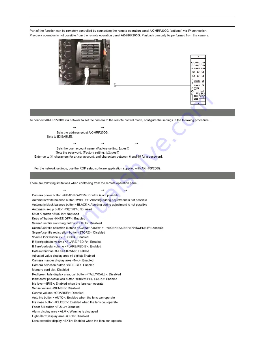
Connecting the remote operation panel (AK-HRP200G)

LAN cable (optional)

AK-HRP200G

Setting for connection with the remote operation panel (AK-HRP200G)

Set each item in [MENU]   [PERIPHERAL]   [LAN PROPERTY] in the camera.

[IP ADDRESS]:
[DHCP]:

Set each item in [MENU]   [PERIPHERAL]   [NETWORK FUNC]   [USER ACCOUNT] in the camera.

[USER NAME]:
[PASSWORD]:

Configure the network settings of AK-HRP200G.

Limitation with the remote control

r

When the [MENU]   [CAMERA SETTINGS]   [Enhanced]   [Enhanced SW] is set to [ON]

f

f

f

f

f

f

f

f

f

f

f

f

f

f

f

f

f

f

f

f

f

f

f

f

f

f

f

f

USO 

RESTRITO

Содержание Varicam HS

Страница 1: ...HS Operating Guide Version 3 W1014HM3045 YI VQT5K86A 3 E USO RESTRITO ...

Страница 2: ...logo is a trademark of SD 3C LLC f f and Windows f f f f owners f f f f How to read this document r Illustrations f r Conventions used in this manual f f r Reference pages f r Terminology f f f f f f USO RESTRITO ...

Страница 3: ...Contents 3 Contents USO RESTRITO ...

Страница 4: ...USO RESTRITO ...

Страница 5: ...Chapter 1 Overview USO RESTRITO ...

Страница 6: ...nsmitters or high voltage devices r When using the camera recorder at the beach etc be careful that sand and dust do not get inside the camera recorder r When carrying the camera recorder be careful not to drop it f r Do not apply insecticide or volatile materials to the camera recorder f f r After using the camera recorder be sure to remove the battery r Take proper care of the battery terminal r...

Страница 7: ... licensed under MIT License 3 This product includes software developed by the OpenSSL Project for use in the OpenSSL Toolkit http www openssl org 4 This product includes software licensed under OpenBSD License 5 This product includes PHP freely available from http www php net 6 This software is based in part on the work of the Independent JPEG Group 7 This product includes software licensed under ...

Страница 8: ... 8 Chapter 1 Overview Accessories Accessories Camera module f Recording module f f f f Slider unit f f f Shoulder mount module f NOTE t USO RESTRITO ...

Страница 9: ...amera on a system Use of the camera on a system Basic system devices Product name Model No 1 1 2 2 3 3 3 3 Expansion system devices Product name Model No Remark LCD monitor Wireless module Accessories Product name Model No USO RESTRITO ...

Страница 10: ...Chapter 2 Description of Parts USO RESTRITO ...

Страница 11: ...ule Left side 1 2 3 4 5 7 6 8 9 1 USER buttons 1 2 3 2 REC button 3 SHUTTER switch 4 EI switch 5 Accessory mounting holes f 6 Handle 7 LOCK switch 8 WB switch 9 Fan inlet Right side 1 3 2 4 5 6 7 9 8 10 11 1 Accessory mounting holes f 2 Fan outlet USO RESTRITO ...

Страница 12: ... 6 Focus hook 7 VF terminal 8 VF SDI terminal 9 DC OUT terminal 10 MIC IN terminal 11 LENS terminal Front 1 2 3 4 5 6 1 Accessory mounting holes f 2 Lens cable microphone cable clamp 3 Lens mount 4 ND FILTER CC FILTER dial A 3200 K B 4300 K C 5600 K D 0 3ND 1 CLEAR 2 0 6ND 3 1 2ND 4 1 8ND 5 Lens lever 6 Mount cap USO RESTRITO ...

Страница 13: ...late 2 Recording module connection terminal Top 1 4 5 1 2 3 1 2 Mounting hole for control panel mounting part 3 Microphone holder mounting position 4 GPS module position 5 Accessory mounting holes f Bottom 1 1 Shoulder mount module tripod mounting holes f USO RESTRITO ...

Страница 14: ...VIEW button 6 Main slot open close switch 7 Control panel operation buttons 8 Control panel 9 MENU button 10 REC button 11 EXIT button 12 POWER switch 13 Jog dial button 14 LOCK switch 15 Cable clamp 16 Open close switch for sub slot and SD memory card slot 17 Main slot lock switch 1 2 18 Main slot 1 2 access LED 19 Main slot 1 2 20 Sub slot 3 4 access LED 21 Sub slot 3 4 USO RESTRITO ...

Страница 15: ...SDI OUT1 SDI OUT2 SDI OUT3 SDI OUT4 terminal 2 Light output terminal 3 USB HOST terminal inside the cover 5 0 V 0 5 A max 4 TC IN OUT terminal 5 GENLOCK IN terminal 6 MON OUT1 MON OUT2 terminal 7 Fan outlet 8 USB DEVICE terminal 9 LAN terminal Front 1 2 1 Lock angle 2 Camera unit connection terminal USO RESTRITO ...

Страница 16: ...ever 3 Battery contact terminals 4 Speaker 5 AUDIO IN 1 AUDIO IN 2 terminal 6 LINE MIC switch LINE MIC 7 PHONES terminal 8 DC OUT RS terminal 9 DC IN terminal 10 LIGHT CONTROL switch Top side 2 1 3 1 Mounting hole for control panel mounting part 2 RELEASE switch 3 External unit connection terminal USO RESTRITO ...

Страница 17: ... 17 Chapter 2 Description of Parts Recording module Bottom 1 1 Shoulder mount module tripod mounting holes f USO RESTRITO ...

Страница 18: ... EVF USER 1 EVF USER 2 buttons menu 2 CAM MENU button 3 EVF MENU button 4 Jog dial 5 Zoom ring 6 Visibility adjustment ring 7 Eye cup Front 1 2 1 Tally LED 2 Connection terminal Rear 1 2 3 4 1 Eye sensor 2 Lock lever 3 USO RESTRITO ...

Страница 19: ... 19 4 Stopper Top 1 2 1 Lock lever left right position 2 Lock lever front back position USO RESTRITO ...

Страница 20: ... mount module Left side 2 3 1 1 Support rod lock knob 2 Accessory attachment rosette f 3 Stopper Right side 2 1 3 1 Support rod lock knob 2 Accessory attachment rosette f 3 Slide rail lock knob Front 1 1 Support rod mounting holes Top 1 1 Slide rail USO RESTRITO ...

Страница 21: ...Chapter 3 Preparation USO RESTRITO ...

Страница 22: ... Fig 1 2 Firmly push in the recording module and connect the connection terminals of the camera module and recording module Fig 2 NOTE t t Disassembling Fig 1 Fig 2 1 Push down the recording module release lever Fig 2 while pulling up the lock knob red of the recording module release lever Fig 1 2 Lift the recording module 3 Remove the upper lock angle in front of the recording module from the upp...

Страница 23: ...e from above into the slider unit Fig 2 3 Push down the lock lever backwards to lock 4 Connect the supplied connecting cable to the viewfinder connection terminal and the camera module s VF terminal Disassembling a a Stopper 1 Remove the connecting cable 2 Push down the lock lever towards the front to release the lock 3 Lift the viewfinder while pulling the stopper 4 Remove the slider unit clampin...

Страница 24: ... to the bottom of the camera with the supplied two screws on the screw holes indicated in the figure Fig 2 4 Slide the camera forward along the groove in the shoulder mount module from the rear until it clicks Fig 3 5 After adjusting the slide position of the camera considering its weight balance lock by turning the slide rail lock knob clockwise Disassembling 1 Release the slide rail lock knob 2 ...

Страница 25: ...oving accessories b a a Eye cup b Attaching a tripod Fig 1 Fig 2 Tripod adaptor Pan head 1 Mount the tripod adaptor on the tripod Fig 1 2 Mount the camera on the tripod adaptor Fig 2 NOTE t Removing the camera from the tripod adaptor Red lever Black lever NOTE t USO RESTRITO ...

Страница 26: ...Chapter 3 Preparation Attaching and removing accessories Attaching the rain cover Tighten the cord Secure with the surface fastener USO RESTRITO ...

Страница 27: ...battery Using Anton Bauer batteries Anton Bauer batteries Release lever 1 Mount the Anton Bauer battery 2 Insert the battery terminal and slide in the direction of the arrow 3 NOTE t Using V mount type batteries Release lever 1 Mount the V mount type battery plate 2 Slide in the direction of the arrow 3 Set the battery type f USO RESTRITO ...

Страница 28: ... DC power supply 1 Connect the external DC power supply to the DC IN terminal of the camera 2 Turn on the power switch of the external DC power supply if the external DC power supply has a power switch 3 Turn the POWER switch of the camera to ON r External DC power supply 2 f DC IN 1 2 3 NOTE t t t t t USO RESTRITO ...

Страница 29: ...ns lever Mount cap Mark Cable clamp LENS terminal 1 Raise the lens lever and remove the mount cap Fig 1 2 Align the indentation at the top center of the lens mount with the center mark of the lens to mount the lens Fig 2 3 Lower the lens lever to firmly clamp the lens Fig 3 4 5 NOTE t t Flange lens back adjustment NOTE t USO RESTRITO ...

Страница 30: ...mping screw 5 Set the zoom ring to the telephoto end position either manually or by electric drive 6 Aim the lens at the lens flange back adjustment chart and turn the distance ring to bring the chart into focus 7 Set the zoom ring to the wide angle end position and turn the F f Flange focus ring to bring into focus 8 9 Firmly tighten the F f Flange focus ring clamping screw NOTE t White shading c...

Страница 31: ...ation Mounting and adjusting the lens 2 Set the screen 1 2 f f f 3 Adjust the white balance black balance 1 f f 2 f f 3 4 5 Adjust white shading 1 6 NOTE t t t t Chromatic aberration compensation function CAC USO RESTRITO ...

Страница 32: ...c aberration B G R is registration error Chromatic aberration compensation function NOTE t Operation of chromatic aberration compensation function 1 Mount the lens on the camera and connect the lens connector to the camera 2 Set MENU CAMERA SETTINGS EXT FUNC CAC to ON USO RESTRITO ...

Страница 33: ... RS terminal to the external recording start stop switch 1 2 3 4 DC OUT RS terminal LED Resistance start stop Connection example Cable connector HR10A 7R 4SC 73 Hirose Electric Co Recording 1 GND 2 TALLY OUT 3 Recording start stop switch 4 12 V NOTE t Connecting to the DC OUT terminal 1 2 1 GND 2 12 V NOTE t USO RESTRITO ...

Страница 34: ... date time of the internal clock 1 Press the MENU button f 2 Select MENU SYSTEM SETTINGS CLOCK 3 Select MENU SYSTEM SETTINGS CLOCK NOTE t r Time zone table Time difference Region Time difference Region Islamabad Dakar Bangkok Denver Darwin Solomon Islands NOTE t t t USO RESTRITO ...

Страница 35: ...Chapter 4 Video Recording and Color Grading USO RESTRITO ...

Страница 36: ...Chapter 4 Video Recording and Color Grading Dual recording Dual recording Main slot Sub slot r Main recorder Card slot 2 f f f r Sub recorder Card slot 2 f f f USO RESTRITO ...

Страница 37: ...Selecting the resolution codec and video format for recording f f f f f f f f f r When MAIN PIXEL is set to 1920 1080 MAIN CODEC FREQUENCY HIGH SPEED VFR Variable range SUB CODEC PROXY r When MAIN PIXEL is set to 1280 720 MAIN CODEC FREQUENCY HIGH SPEED VFR Variable range SUB CODEC PROXY NOTE t t t USO RESTRITO ...

Страница 38: ...Recording and Color Grading In camera grading In camera grading Grading function f f f f Control combinations through settings MAIN COLOR Grading SEL SUB COLOR CDL Output Picture Adjustment MON 1 MON 2 EVF LCC USO RESTRITO ...

Страница 39: ...n slot 2 Sub slot card access LED Sub slot 3 Card slot cover Fig 1 Fig 2 Fig 3 Main slot lock switch Eject button 1 Open the card slot cover Fig 1 2 Insert a card into the card slot Fig 2 f f 3 f Example When expressP2 memory cards are inserted in two slots 2 1 4 Close the cover of the main slot or sub slot NOTE t t t t t t USO RESTRITO ...

Страница 40: ...Fig 2 1 Open the card slot cover 2 Remove the card f f NOTE t t t t t t Preventing accidental erasure side Write protect switch Write protect switch NOTE t Card access LEDs and P2 card status Card access LED P2 card status Illuminated in green Illuminated in orange USO RESTRITO ...

Страница 41: ...ain recording format MAIN CODEC Setting conditions Recording time when using a 256 GB expressP2 memory card r Sub recorder Sub recording format SUB CODEC Setting conditions Recording time when using a 64 GB microP2 memory card NOTE t Dividing clips recorded on P2 cards Recording format excluding native recording Continuous recording time CPS Content Protection System NOTE t t t USO RESTRITO ...

Страница 42: ...te it to the SD memory card 3 Load the CPS password file 1 2 3 f f t Setting CPS password using the menu of the camera 1 Open the thumbnail screen and select SET from MENU SYSTEM SETTINGS CARDS MEDIA CPS PASSWORD 2 Enter the CPS password with the keyboard f f t t Deleting CPS password 1 Open the thumbnail screen and select DELETE from MENU SYSTEM SETTINGS CARDS MEDIA CPS PASSWORD NOTE t How to han...

Страница 43: ...ay no longer be recognized as P2 data or the card may no longer be able to be used with P2 devices This is the file to which the information of the final clip that was recorded with the P2 device is written NOTE t t t overwritten Formatting a P2 card 1 Select the slot of the memory card you want to format from MENU SYSTEM SETTINGS CARDS MEDIA FORMAT CARD f 2 Select YES using the jog dial button NO...

Страница 44: ... the button to which the shot mark is assigned f f NOTE t Text memo recording function Adding text memos 1 From MENU SYSTEM SETTINGS USER SWITCHS set TEXT MEMO for any setting from USER1 to USER4 2 During a pause or while a clip is selected in the PLAY screen press the button to which the text memo is assigned NOTE t Pre recording Operation to start recording Operation to stop recording Actual rec...

Страница 45: ...AL TIME 1 Set MENU REC SETTINGS REC FUNCTION REC MODE to INTERVAL 2 Set the following related items from MENU REC SETTINGS REC FUNCTION f f 3 Press the REC button f f f f NOTE t t t t One shot recording 1 Set MENU REC SETTINGS REC FUNCTION REC MODE to ONE SHOT f f 2 Set the following related items from MENU REC SETTINGS REC FUNCTION f f 3 Press the REC button f f f f NOTE t t t t t USO RESTRITO ...

Страница 46: ...Chapter 5 Control Panel USO RESTRITO ...

Страница 47: ... TC button d INFO button e VIEW button f EXIT button g MENU button h Jog dial button i LOCK switch j Control panel operation buttons Camera status display 1 2 3 4 5 6 7 8 9 1 Recording status display f f 2 Media free space display f f f f f 3 Codec display 4 Battery display f f f f f 5 Audio level meter display USO RESTRITO ...

Страница 48: ...f f f 8 USER CLIP NAME TYPE3 display 9 Lock display network status display Using the control panel extension unit Fig 1 Fig 2 Fig 3 1 Press the RELEASE switch while lifting up the control panel Fig 1 2 Attach the control panel extension unit Fig 2 3 Connect the control panel extension unit cable to the control panel Fig 3 USO RESTRITO ...

Страница 49: ...g the control panel using the control panel mounting part Fig 1 Fig 3 Fig 2 1 Mount the control panel mounting part Fig 1 2 Mount the control panel onto the control panel mounting part Fig 2 3 Secure the control panel using screws Fig 3 NOTE t USO RESTRITO ...

Страница 50: ...Chapter 5 Control Panel HOME screen HOME screen f f f USO RESTRITO ...

Страница 51: ...Chapter 5 Control Panel HOME screen f f USO RESTRITO ...

Страница 52: ...Chapter 5 Control Panel PLAY screen PLAY screen USO RESTRITO ...

Страница 53: ...Chapter 5 Control Panel TC screen TC screen USO RESTRITO ...

Страница 54: ...Chapter 5 Control Panel INFO screen INFO screen USO RESTRITO ...

Страница 55: ...Chapter 5 Control Panel VIEW screen VIEW screen USO RESTRITO ...

Страница 56: ...Chapter 5 Control Panel MENU screen MENU screen USO RESTRITO ...

Страница 57: ...Chapter 6 Audio recording USO RESTRITO ...

Страница 58: ...nd tighten the clamping screw a Fig 2 3 Loosen the lock lever b adjust the angle of the microphone and tighten the lock lever Fig 3 4 Connect the microphone cable to the MIC IN terminal on the camera module Fig 4 5 According to the audio channel to be recorded select FRONT in control panel audio input Setting the audio input using the control panel 1 Press the HOME button to display the HOME scree...

Страница 59: ...erminal of the recording module using the XLR cable 2 According to the channel to which the XLR cable is connected select REAR in control panel audio input 3 Switch the LINE MIC switch on the AUDIO IN 1 terminal or AUDIO IN 2 terminal to LINE Setting the control panel 1 Press the HOME button to display the HOME screen 2 From SYSTEM AUDIO select AUDIO IN 3 Select REAR in CH1 2 IN NOTE t USO RESTRIT...

Страница 60: ...tton to display the HOME screen 2 From SYSTEM AUDIO select AUDIO IN 3 Select FRONT in CH1 2 IN NOTE t t Adjusting the recording levels Automatic adjustment 1 Press the HOME button to display the HOME screen 2 From SYSTEM AUDIO select AUDIO IN 3 Select AUTO in FRONT1 LEVEL or FRONT2 LEVEL Manual adjustment same manner 1 Press the HOME button to display the HOME screen USO RESTRITO ...

Страница 61: ...using FRONT1 FRONT1 or FRONT2 FRONT2 while viewing the audio channel level meter display r Recording standard level NOTE t Audio monitor headphones 1 Press the HOME button to display the HOME screen 2 From SYSTEM AUDIO select AUDIO OUT r Setting the headphones output audio 1 Select the output signal mono stereo mix in MONITOR r Adjusting the headphones output audio level 1 Adjust with the MON MON ...

Страница 62: ...Chapter 7 USO RESTRITO ...

Страница 63: ...ns 2 Slide the viewfinder from side to side 3 Lock the lock lever left right position r Front back position adjustment 1 Loosen the lock lever front rear positions 2 Slide the viewfinder back and forth 3 Lock the lock lever front back position r Visibility adjustment 1 Turn the visibility adjustment ring while pressing holding the upper button r Zoom adjustment 1 Adjust by turning the zoom ring US...

Страница 64: ...e jog dial button to make adjustments 5 Press the jog dial button 6 Press the EVF MENU button Direct camera settings 1 Press the CAM MENU button of the viewfinder 2 Turn the jog dial button to select the items you want to set 3 Press the jog dial button 4 Turn the jog dial button to select setting details 5 Press the CAM MENU button 1 Press and hold the CAM MENU button of the viewfinder for at lea...

Страница 65: ...32 31 f 32 31 f 32 31 f 0 9 f 32 31 f 32 31 f 32 31 f r SW MODE Item Description of settings ON OFF NORMAL 1min 5min ON OFF NORMAL REVERSE r USER SW 1 USER SW 2 Description of settings MARKER CENTER MARKER SAFETY MARKER FRAME MARK USER BOX ZEBRA EXPAND ASSIST FALSE COLOR SMOOTH MODE WFM r INFORMATION Item Description of settings USO RESTRITO ...

Страница 66: ...False color mode Display patterns r When MAIN COLOR is V Log Color Level Description Blue r When MAIN COLOR is not V Log Color Level Description Blue USO RESTRITO ...

Страница 67: ...ion of settings terminal ON OFF f ON SPOT OFF f 0 109 f 0 109 f ZEBRA2 Image level ON OFF SPOT 109 ZEBRA2 DETECT ZEBRA1 DETECT 0 Displaying the center marker Displaying the safety zone marker Displaying frame marker Focus assist function Expanded display USO RESTRITO ...

Страница 68: ...ction Peaking display focus in red NOTE t Focus square display When focused on the doll When focused on the panel NOTE t Focus bar display f f Not in focus The bar extends to the right when the viewfinder is in focus NOTE t USO RESTRITO ...

Страница 69: ...Chapter 8 Output and Screen Display USO RESTRITO ...

Страница 70: ...r 8 Output and Screen Display SDI output SDI output Output format list SYSTEM MODE VFR SW SDI OUT Output Format PIXEL MAIN CODEC HIGH SPEED P to PsF Signal Format 1 1 2 1 1 1 1 1 1 2 1 2 1 1 1 2 USO RESTRITO ...

Страница 71: ...71 Chapter 8 Output and Screen Display SDI output SYSTEM MODE VFR SW SDI OUT Output Format PIXEL MAIN CODEC HIGH SPEED P to PsF Signal Format 1 1 2 1 2 1 1 2 1 1 2 1 1 1 1 1 3 2 3 2 1 1 1 2 USO RESTRITO ...

Страница 72: ... 72 Chapter 8 Output and Screen Display SDI output SYSTEM MODE VFR SW SDI OUT Output Format PIXEL MAIN CODEC HIGH SPEED P to PsF Signal Format 1 3 2 3 2 1 1 2 1 1 1 1 1 USO RESTRITO ...

Страница 73: ... 73 Chapter 8 Output and Screen Display MON OUT1 output MON OUT1 output Output format list SYSTEM MODE MON OUT1 Output Format FREQUENCY PIXEL MAIN CODEC MON OUT FORMAT Signal Format USO RESTRITO ...

Страница 74: ...er 8 Output and Screen Display MON OUT2 output MON OUT2 output f Output format list SYSTEM MODE MON OUT2 Output Format FREQUENCY PIXEL MAIN CODEC MON OUT2 SIGNAL SEL 1080p to 1080i Signal Format USO RESTRITO ...

Страница 75: ...Chapter 8 Output and Screen Display MON OUT2 output SYSTEM MODE MON OUT2 Output Format FREQUENCY PIXEL MAIN CODEC MON OUT2 SIGNAL SEL 1080p to 1080i Signal Format USO RESTRITO ...

Страница 76: ...Chapter 8 Output and Screen Display VF SDI output VF SDI output Output format list SYSTEM MODE VF SDI DISPLAY Output Format FREQUENCY VF SDI 1080p to 1080i Signal Format USO RESTRITO ...

Страница 77: ... recorder recording status 4 Main codec 5 Sub recorder recording status 6 Sub codec 7 Card remaining free space 8 Battery charge level 9 Time code 10 Warning 11 Proxy 12 Clip name 13 Focus bar only output from VF SDI terminal 14 FPS 15 Shutter 16 EXPOSURE INDEX 17 White balance 18 Y GET 19 Iris 20 Focus position 21 Zoom 22 23 Extender 24 Recording mode to be supported 25 GPS status USO RESTRITO ...

Страница 78: ...ixel 3 System frequency 4 Battery charge level 5 Main recorder recording status 6 Main codec 7 Sub recorder recording status 8 Sub codec 9 Proxy 10 Time code 11 Recording mode to be supported 12 Iris 13 FPS 14 15 Shutter 16 Y GET 17 EXPOSURE INDEX 18 Clip name 19 White balance 20 Focus position 21 GPS status 22 Zoom 23 Extender USO RESTRITO ...

Страница 79: ...Chapter 9 Other Useful Functions USO RESTRITO ...

Страница 80: ...ter 9 Other Useful Functions Getting position information using the GPS Getting position information using the GPS f f f f NOTE t t t t large margin of errors Indoors In forests Inside tunnels USO RESTRITO ...

Страница 81: ...er Useful Functions Assigning functions to the USER buttons Assigning functions to the USER buttons USER2 USER5 USER6 USER8 USER10 USER1 USER3 USER4 USER7 USER9 Selectable functions Item Description NOTE t USO RESTRITO ...

Страница 82: ...a File types r f f r f f ins r f 32 f abr Handling SD memory cards Inserting SD memory cards Fig 1 Fig 2 1 Open the slot cover Fig 1 2 Insert the SD memory card into the SD memory card slot with the label side of the card upward and close the slot cover Fig 2 NOTE t t USO RESTRITO ...

Страница 83: ...points when using or storing memory cards f f f Performing operations on SD memory cards Formatting SD memory cards 1 From MENU SYSTEM SETTINGS CARDS MEDIA FORMAT CARD select SD CARD and press the jog dial button 2 Select YES on the confirmation screen and press the jog dial button 3 NOTE t USO RESTRITO ...

Страница 84: ...ngth counter r Date time real time f f f Item USER TIME DATE EXT INPUT TCG FRAME RATE How to input user bits 1 Press the TC button to display the TC screen 2 From the user bits display select User in UB MODE 3 Select SET 4 Set the user bits using the jog dial button 5 Press the jog dial button to confirm the user bits setting value NOTE t USO RESTRITO ...

Страница 85: ...ark Camera image mode Example During shooting VFR 30PN or over 60P VFR over 60P VFR24PN during shooting VFR25PN or over 50P Setting the time code 1 Press the TC button to display the TC screen 2 From the time code display select DF or NDF in DF NDF 3 Select SET 4 Set the time code using the jog dial button 5 Press the jog dial button to confirm the time code setting value Settable time code range ...

Страница 86: ...C button to display the TC screen 2 From the time code display select Free Run in Free Rec 3 From MENU REC SETTINGS TC TC IN OUT SEL select TC IN 4 Enter the external time code from the TC IN OUT terminal f f f f f f f Cautions when switching the power supply from the battery to the external power supply while an external lock is active Supplying the time code externally USO RESTRITO ...

Страница 87: ...SDI OUT2 SDI OUT3 SDI OUT4 terminal VIDEO IN terminal SDI IN terminal HD SDI IN terminal TC IN terminal VTR etc r When two cameras are connected and one is used as a reference camera TC IN OUT terminal Reference camera Slave camera TC IN OUT terminal SDI OUT1 terminal GENLOCK IN terminal NOTE t t Operating procedure 1 From MENU REC SETTINGS TC TC IN OUT SEL set TC OUT f f USO RESTRITO ...

Страница 88: ...CE terminal Connection through the USB DEVICE terminal Connecting to a computer in the USB device mode Connecting to a computer Fig 1 1 Connect the USB cable to the USB DEVICE terminal device Fig 1 2 Set the MENU 3 Exit the USB device mode f f NOTE t t t t USO RESTRITO ...

Страница 89: ...Chapter 10 Menu Operations USO RESTRITO ...

Страница 90: ...Chapter 10 Menu Operations Setting menu structure Setting menu structure Enhanced menu USO RESTRITO ...

Страница 91: ...button to place the cursor on the desired menu item f 3 Press the jog dial button f f 4 Turn the jog dial button to place the cursor on the desired item 5 Press the jog dial button 6 Turn the jog dial button to place the cursor on the desired item 7 Press the jog dial button 8 Press the EXIT button to close the menu Setting menu initialization 1 Select LOAD FACTORY DATA from MENU SYSTEM SETTINGS I...

Страница 92: ...20 f setting AVC Intra444 AVC Intra200 AVC Intra100 ProRes 4444 ProRes 422 HQ f setting AVC Intra100 AVC LongG50 AVC LongG25 AVC Intra100 Pxy AVC LongG50 Pxy AVC LongG25 Pxy OFF f VFR up to 60p 50p NORMAL Audio f ON fps OFF 1 fps f V Log V 709 F REC HD f Internal OFF External App f V Log GRADING V Log V 709 V 709 F REC HD f OFF V 709 OFF f ON OFF OFF f USO RESTRITO ...

Страница 93: ... V 709 F REC LCC HD f V Log GRADING V Log V 709 V 709 F REC LCC HD f V Log GRADING V 709 LCC V Log V 709 LCC V 709 F REC LCC HD f ON OFF f ON OFF f 40dB 50dB f ON OFF f ON OFF f 40dB 50dB 60dB f 4dB 0dB 3dB f ON OFF f ON OFF f ON OFF f ON OFF f 1t2FRONT 3t4REAR 1t2REAR 3t4FRONT f t t USO RESTRITO ...

Страница 94: ...AL f AUTO MANUAL f AUTO MANUAL f AUTO MANUAL f 0 100 f 0 100 f 0 100 f 0 100 f ON OFF f ON OFF f ON OFF f ON OFF f 18dB 20dB f CH1 2 CH3 4 f MONO CH1 MONO CH2 STEREO CH1 2 MIX CH1 2 MONO CH3 MONO CH4 STEREO CH3 4 MIX CH3 4 f ON OFF f 0 100 f LOUD MIDIUM SMALL OFF f 15 15 f USO RESTRITO ...

Страница 95: ... settings 15 15 f 30 30 f 1 0 1 f ON OFF f ON OFF f f f ON OFF f LEVEL A LEVEL B f ON OFF f 1920 over p 1920 over i 1920 PsF 1080i 720p f LEVEL A LEVEL B f VF Always 1080p MON OUT1 f ON OFF f ON OFF f ON OFF f ON OFF f ON OFF f ON OFF f ON OFF f USO RESTRITO ...

Страница 96: ...settings ON OFF f ON OFF f ON OFF f ON OFF f ON OFF f ON OFF f ON OFF f ON OFF f ON OFF f ON OFF f ON OFF f TCG TCR TCG OFF f ON OFF f ON OFF f ON OFF f ON OFF f ON OFF f ON OFF f ON OFF f ON OFF f ON OFF f 1 large 2 3 medium 4 5 small 6 7 OFF f USO RESTRITO ...

Страница 97: ... ON OFF f 1 100 f 1 100 f 50 50 f 50 50 f INT EXT f 100 100 f 100 100 f VERSION MODEL NAME SERIAL NO LOAD SET DELETE MAIN SLOT1 MAIN SLOT2 SUB SLOT3 SUB SLOT4 SD CARD ON OFF f INHIBIT SIX USER BUTTONS AWB ABB Y GET DRS EXPAND ASSIST WFM BARS FALSE COLOR VF COLOR MON1 COLOR MON2 COLOR SMOOTH MODE TEXT MEMO SHOT MARK MAIN SLOT SEL SUB SLOT SEL REC SW f USO RESTRITO ...

Страница 98: ...LOR VF COLOR MON1 COLOR MON2 COLOR SMOOTH MODE TEXT MEMO SHOT MARK MAIN SLOT SEL SUB SLOT SEL REC SW f INHIBIT EXPAND ASSIST FALSE COLOR VF COLOR MON1 COLOR MON2 COLOR SMOOTH MODE f INHIBIT EXPAND ASSIST FALSE COLOR VF COLOR MON1 COLOR MON2 COLOR SMOOTH MODE f INHIBIT EXPAND ASSIST FALSE COLOR VF COLOR MON1 COLOR MON2 COLOR SMOOTH MODE f INHIBIT EXPAND ASSIST FALSE COLOR VF COLOR MON1 COLOR MON2 C...

Страница 99: ... 4 5 6 7 8 9 10 12 14 16 18 20 f 1 10 f 13 0V 17 0V f terminal 11 0V 15 0V f 11 0V 15 0V f ON OFF f YEAR MONTH DAY HOUR MINUTE 12 00 13 00 Y M D M D Y D M Y f REC AUTO MATCH CODEC ALWAYS FULL f YES NO CAMERA SETTINGS Item Description of settings ON OFF f ON OFF f PRESET VARIABLE f f f USO RESTRITO ...

Страница 100: ...on of settings EXECUTE CANCEL f PRESET TEMP SHIFT f f 2300K 15000K f 10 10 f 200 200 f 200 200 f ON OFF f OFF 1 2 3 f EXECUTE CANCEL f 100 100 f 100 100 f 100 100 f 100 100 f ON OFF f ON OFF f 100 100 f 100 100 f 100 100 f ON OFF f ISO dB f USO RESTRITO ...

Страница 101: ...10000 12800 f 0dB 3dB 6dB 9dB 12dB 15dB 18dB 21dB 24dB f ON OFF f 0 0dB 0 9dB f ON OFF f sec deg f PRESET SYNCHRO f 1 0 358 0 f 1 60 1 250 f f f OFF BARS f SMPTE FULL f 0 35 0 90 f x4 0 x4 5 x5 0 x5 5 f 8 1 OFF Standard state 1 8 f 10 20 30 f ON OFF f D RANGE PRESS f 75 109 f 0 100 f USO RESTRITO ...

Страница 102: ...ption of settings 200 300 400 500 600 f 0 30 f ON OFF f NORMAL SKIN HOLD f 1 5 f ON OFF f 90 109 f ON OFF f 0 63 f 0 31 f R G 2 2G R B 4 3G R 4 R G f 0 63 f 0 31 f 0 60 f 31 31 f 31 31 f 0 63 f 31 31 f ON OFF f 1 5 f ON OFF f 1 5 f 1 5 f USO RESTRITO ...

Страница 103: ...gs 1 5 f OFF ON f A B C A B A C B C A B C f EXECUTE CANCEL ON OFF f 0 31 f A B C f 0 255 f 0 255 f 0 127 f 0 255 f ON OFF f 127 127 f 127 127 f 127 127 f 127 127 f 127 127 f 127 127 f 127 127 f 127 127 f 127 127 f 127 127 f 127 127 f 127 127 f ON OFF f USO RESTRITO ...

Страница 104: ...st Item Description of settings 63 63 f 63 63 f 63 63 f 63 63 f 63 63 f 63 63 f 63 63 f 63 63 f 63 63 f 63 63 f 63 63 f 63 63 f 63 63 f 63 63 f 63 63 f 63 63 f 63 63 f 63 63 f 63 63 f 63 63 f 63 63 f 63 63 f 63 63 f 63 63 f USO RESTRITO ...

Страница 105: ...F f 63 63 f 63 63 f ON OFF f 1 32 f ON OFF f Meter Feet f LENS CAM f 0 100 f 1 20 f NORMAL1 NORMAL2 CENTER f 0 100 f ON OFF f R G B f 255 255 f 255 255 f 255 255 f 255 255 f REC SETTINGS Item Description of settings NORMAL INTERVAL ONE SHOT f 00s01f 59s23f f f USO RESTRITO ...

Страница 106: ...0f f 0s 10s f ON OFF f f f ONE FILE SPLIT f 00 23 00 59 00 59 00 23 00 23 00 29 f f TC UB Dur f FREE RUN REC RUN f DF NDF f FRAME RATE USER EXT INPUT TIME DATE f TC IN TC OUT f TCG TCG TCR f RECORDING SDI OUT f ON OFF Does not add metadata f TYPE1 TYPE2 TYPE3 TYPE1 TYPE2 TYPE3 f USO RESTRITO ...

Страница 107: ...ATE SENSOR FPS SHUTTER EI COLOR TEMP f NONE CUSTOM BURN DATA1 CUSTOM BURN DATA2 CUSTOM BURN DATA3 CAM INDEX REEL COUNT CLIP NAME USER CLIP NAME TYPE3 SHOOT DATE SENSOR FPS SHUTTER EI COLOR TEMP f NONE CUSTOM BURN DATA1 CUSTOM BURN DATA2 CUSTOM BURN DATA3 CAM INDEX REEL COUNT CLIP NAME USER CLIP NAME TYPE3 SHOOT DATE SENSOR FPS SHUTTER EI COLOR TEMP f NONE CUSTOM BURN DATA1 CUSTOM BURN DATA2 CUSTOM...

Страница 108: ...cription of settings ON OFF f VF VF SDI VF VF SDI f 1 large 2 3 medium 4 5 small 6 7 OFF f 1 2 Corners OFF f 80 100 f ON OFF f 1 33 1 1 44 1 1 56 1 1 78 1 1 85 1 2 35 1 f 0 100 f 50 60 70 f ON OFF f 1 100 f 1 100 f 50 50 f 50 50 f terminal ON OFF f VF VF SDI VF VF SDI f ON SPOT OFF f 0 109 f USO RESTRITO ...

Страница 109: ...tion of settings 0 109 f ON OFF f VF VF SDI VF VF SDI f ON OFF f f ON OFF f ON OFF f ON OFF f ON OFF f ON OFF f ON OFF f ON OFF f ON OFF f ON OFF f ON OFF f ON OFF f ON OFF f ON OFF f TCG TCR TCG OFF f ON OFF f ON OFF f ON OFF f ON OFF f USO RESTRITO ...

Страница 110: ... f ON OFF f ON OFF f ON OFF f ON OFF f VF VF SDI VF VF SDI f ON OFF f ON OFF f ON OFF f 0 8 f x2 x3 x4 f 10SEC HOLD UNTIL REC f LOW MID HIGH f RED GREEN WHITE f ON OFF f VF VF SDI VF VF SDI f ON OFF f ON OFF f ON OFF f VF VF SDI VF VF SDI f 0 25 50 75 f STOP f S M L f USO RESTRITO ...

Страница 111: ... Description of settings ON OFF f VF VF SDI VF VF SDI f FILE Item Description of settings PERIPHERAL Item Description of settings ON OFF f network LAN WLAN OFF f ENABLE DISABLE f f f f f f ENABLE DISABLE f AUTO CH1 CH6 CH11 f digits f USO RESTRITO ...

Страница 112: ... 112 Chapter 10 Menu Operations Menu list Item Description of settings f f ENABLE DISABLE f USO RESTRITO ...

Страница 113: ... 113 Chapter 10 Menu Operations Menu operations Menu operations r Operation f f f f l f SYSTEM SETTINGS Item Operation UI SW VF l l l l l l l l l l l l l l l l l l l l l l l l l l l l l l l USO RESTRITO ...

Страница 114: ...Chapter 10 Menu Operations Menu operations Item Operation UI SW VF l l l l l l l l l USO RESTRITO ...

Страница 115: ...Chapter 10 Menu Operations Menu operations Item Operation UI SW VF l l l l l l l l l l CAMERA SETTINGS Item Operation UI SW VF l l l l l l l l l l l l l l l l l l l l l l l USO RESTRITO ...

Страница 116: ...Chapter 10 Menu Operations Menu operations Item Operation UI SW VF l l l l l l l l l l l l l l l USO RESTRITO ...

Страница 117: ... 117 Chapter 10 Menu Operations Menu operations Item Operation UI SW VF REC SETTINGS Item Operation UI SW VF USO RESTRITO ...

Страница 118: ... 118 Chapter 10 Menu Operations Menu operations Item Operation UI SW VF l l l l l l l l l l l l l l l l l l l l l l l l l l l VF SDI SETTINGS Item Operation UI SW VF l l l l l l USO RESTRITO ...

Страница 119: ... 119 Chapter 10 Menu Operations Menu operations Item Operation UI SW VF l l l l l l l l l l l l FILE Item Operation UI SW VF USO RESTRITO ...

Страница 120: ...Chapter 10 Menu Operations Menu operations PERIPHERAL Item Operation UI SW VF l l USO RESTRITO ...

Страница 121: ...Chapter 11 Network Connection USO RESTRITO ...

Страница 122: ... 122 Chapter 11 Network Connection Network connection Network connection 100BASE TX 10BASE T IEEE802 11g n Available functions f f NOTE t USO RESTRITO ...

Страница 123: ...g 2 Fig 3 1 Push the lever down and open the cover Fig 1 Fig 2 2 Connect the wireless module to the USB HOST terminal Fig 3 3 Close the cover NOTE t Cautions when using wireless module f f r For use overseas f f f f NOTE t For wired LAN 1 Connect the LAN cable to the LAN terminal on the right side USO RESTRITO ...

Страница 124: ...N 3 Select SSID from the list of the access points for mobile devices or computers and enter the password encryption key f f 4 Check the network connection NOTE t Wired LAN settings 1 Set each item in MENU PERIPHERAL LAN PROPERTY as necessary MAC ADDRESS DHCP ENABLE DISABLE IP ADDRESS SUBNET MASK DEFAULT GATEWAY PRIMARY DNS SECONDARY DNS DHCP SERVER ENABLE DISABLE 2 Select LAN in MENU PERIPHERAL N...

Страница 125: ...ttings NOTE t Checking network setting Check in the MENU screen Fig 1 1 Select STATUS DISPLAY in MENU PERIPHERAL NETWORK TOOLS Check in the INFO screen Fig 1 1 Press the INFO button to display the INFO screen 2 Select PERIPHERAL USO RESTRITO ...

Страница 126: ...2 Select NETWORK in PERIPHERAL 3 Select LAN WLAN or OFF LAN WLAN OFF Operating user account r Setting user account 1 Select MENU PERIPHERAL NETWORK FUNC USER ACCOUNT r Checking user account 1 Select MENU PERIPHERAL NETWORK FUNC ACCOUNT LIST NOTE t t t r Initializing network settings 1 Select INITIALIZE in MENU PERIPHERAL NETWORK TOOLS USO RESTRITO ...

Страница 127: ...ion panel AK HRP200G 1 Set each item in MENU PERIPHERAL LAN PROPERTY in the camera IP ADDRESS DHCP 2 Set each item in MENU PERIPHERAL NETWORK FUNC USER ACCOUNT in the camera USER NAME PASSWORD 3 Configure the network settings of AK HRP200G Limitation with the remote control r When the MENU CAMERA SETTINGS Enhanced Enhanced SW is set to ON f f f f f f f f f f f f f f f f f f f f f f f f f f f f USO...

Страница 128: ...rk Connection Connecting the remote operation panel AK HRP200G f r When the MENU CAMERA SETTINGS Enhanced Enhanced SW is set to OFF f f f f f f f f f About adjusted value display area 4 digits NOTE t t t t t t USO RESTRITO ...

Страница 129: ...Chapter 12 Maintenance and Inspection USO RESTRITO ...

Страница 130: ...ry card or P2 memory card into the main slot and close the slot cover 4 Set the POWER switch to ON 5 Check the remaining battery level with the status display on the control panel 6 Check the media free space with the status display on the control panel 7 Press the REC button and check the following f f f 8 Press the REC button again 9 Press the PLAY button to switch to the PLAY screen and play ba...

Страница 131: ... 131 Chapter 12 Maintenance and Inspection Maintenance Maintenance Charging the built in battery USO RESTRITO ...

Страница 132: ...ror codes Error code Display Description Behavior and cause f f f f f f f f f f f f f f f f f f f f f f f f f Cases indicated by error messages During recording playback Display Description Behavior and cause f on f f f f f f f f to use it again f f f f f assured is inserted f f f f USO RESTRITO ...

Страница 133: ...pection Warning system Display Description Behavior and cause f f f f f f f f f f f f f f f f f f f f f f be divided f f f normal During thumbnail and menu operation Display Description Behavior and cause formatting reasons USO RESTRITO ...

Страница 134: ...Chapter 12 Maintenance and Inspection Warning system Display Description Behavior and cause During soft keyboard operation Display Description Behavior and cause USO RESTRITO ...

Страница 135: ... card 3 Insert the SD memory card containing the firmware into the SD memory card slot of the recording module 4 Turn the power on 5 Press the INFO button to display the INFO screen Fig 1 6 Select VERSION 7 Press the jog dial button 8 When UPDATE appears select UPDATE OK NOTE t t t USO RESTRITO ...

Страница 136: ...g and storing Cleaning and storing Cleaning the camera recorder f f f Cautions when storing the camera recorder r Camera body f r Battery f f f f r expressP2 memory card P2 memory card f f r microP2 memory card SD memory card f f f f USO RESTRITO ...

Страница 137: ...Chapter 13 USO RESTRITO ...

Страница 138: ...r 179 mm 7 1 16 inches 127 2 mm 5 1 32 inches 287 7 mm 11 11 32 inches 347 mm 13 11 16 inches 94 mm 3 23 32 inches 111 mm 4 3 8 inches 110 mm 4 11 32 inches 254 mm 10 inches 60 mm 2 3 8 inches General Dimensions W D f USO RESTRITO ...

Страница 139: ... 139 Camera unit 3 Lens mount f f f f f f Memory card recorder f f f f f f f f Digital video f f f Digital audio USO RESTRITO ...

Страница 140: ...Proxy Video input output Audio input output 1 Other input output 1 f f USO RESTRITO ...

Страница 141: ...Index Index A B C D E F G H I Mounting Setting menu Inserting Settings Status Inserting USO RESTRITO ...

Страница 142: ...U V W Z USO RESTRITO ...

Страница 143: ...USO RESTRITO ...

Отзывы: