


31
9.16. Remove the Hanger metals and
the One leg bracket
1. Remove the Plasma panel section from the servicing
stand and lay on a flat surface such as a table (covered
by a soft cloth) with the Plasma panel surface facing
downward.
2. Remove the One leg bracket fastening screws (
×
4 )
and the One leg bracket.
3. Remove the Hanger metals (L, R) fastening screws (
×
2
each) and remove the Hanger metals (L, R).
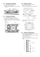
9.17. Remove the Cabinet mount
metals
1. Remove the One leg bracket. (See section 9.16.)
2. Remove the Cabinet mount metals fastening screws (
×
10
,
×
20
) and remove the Cabinet mount metal top
and the Cabinet mount metal bottom.
9.18. Remove the D-Board
1. Remove the AC inlet. (See section 9.1.)
2. Remove the Woofer. (See section 9.9.)
3. Disconnect the flexible cables (D5, D20, D31, D32, D33
and D34).
4. Disconnect the connectors (D3 and D25).
5. Remove the screws (
×
4
) and remove the D-Board.
Содержание TXP50VT20L
Страница 24: ...24 7 4 No Picture ...
Страница 46: ...46 ...
Страница 48: ...48 12 3 Wiring 2 12 4 Wiring 3 ...
Страница 49: ...49 12 5 Wiring 4 ...
Страница 50: ...50 12 6 Wiring 5 ...
Страница 51: ...51 13 Schematic Diagram 13 1 Schematic Diagram Note ...
Страница 102: ...102 14 Printed Circuit Board 14 1 P Board A B C D E F G H I 1 2 3 4 5 6 P BOARD FOIL SIDE ETX2MM806MVH ...
Страница 104: ...104 A B C D E F G H I 1 2 3 4 5 6 P BOARD COMPONENT SIDE ETX2MM806MVH ...
Страница 122: ...122 15 1 2 Exploded View 2 ...
Страница 123: ...123 15 1 3 Packing 1 ...
Страница 124: ...124 15 1 4 Packing 2 ...
Страница 125: ...125 15 1 5 Mechanical Replacement Parts List ...
Страница 129: ...129 15 2 Electrical Replacement Parts List 15 2 1 Replacement Parts List Notes ...


