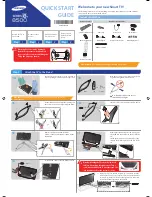
background image

29

10 Block Diagram

10.1. Main Block Diagram

HOT

(LED:6TIMES)

COLD

(LED:7TIMES)

(LED:8TIMES)

SOUND15V

C14

VSUS

SOS8_SS

P

DATA DRIVER (LEFT)

DATA
DRIVER

VIDEO DATA

VSUS

P2

DATA
DRIVER

P35

SOS7_SC2

C20

VDA

SUSTAIN

DATA
DRIVER

VDA

SUSTAIN DRIVE

SCAN DRIVE

DATA
DRIVER

C1

DATA
DRIVER

VSUS

DATA DRIVER (RIGHT)

P3.3V

BUFFER

SUSTAIN CONTROL

SS33

P9

P5V

P15V

DATA
DRIVER

ENERGY RECOVERY

SN20

DATA
DRIVER

DATA
DRIVER

SN

VSUS

CONTROL
PULSE

C22

VAD GEN.

RELAY

SCAN CONTROL

(LOWER)

DATA
DRIVER

SOS6_SC1

VSCAN GEN.

OPERATION
KEYS

VSUS GEN.

SCAN
DRIVER

DATA
DRIVER

DATA
DRIVER

STB5V

RECTIFIER

C10

P+15V

SN2

VDA

DATA
DRIVER

VIDEO DATA

SN-BOARD
ENERGY RECOVERY
SOS DETECT

VSUS

C21

VIDEO DATA

SS

P3.3V

SCAN
DRIVER

STANDBY
VOLTAGE
CONVERTER

SOS8_SS

VDA

AC CORD

SUSTAIN
VOLTAGE
CONVERTER

P11

RECTIFIER

F15V

P5V

OUT

POWER
FACTOR
CONTROL

DATA
DRIVER

SS2

CONTROL UNIT ASSY

PROCESS
VOLTAGE
CONVERTER

SS11

VE GEN.

DATA
DRIVER

VIDEO DATA

SUSTAIN CONTROL

POWER SUPPLY

P3.3V

C2

P3.3V

DATA
DRIVER

KEY3

KEYSCAN

POWER SW

KEY3

KEYSCAN

P5V

P15V

P15V

SN-BOARD
SCAN DRIVE
SOS DETECT

SS-BOARD
SUSTAIN DRIVE
SOS DETECT

C15

F15V

P6

SOUND15V

P15V

STB5V

PANEL_
MAIN_ON

HOT

(LED:6TIMES)

COLD

(LED:7TIMES)

(LED:8TIMES)

(LED:7TIMES)

(LED:10TIMES)

(LED:8TIMES)

(LED:12TIMES)

(LED:6TIMES)

(LED:2TIMES)

(LED:9TIMES)

(LED:10TIMES)

(LED:6TIMES)

P

P

BLUETOOTH

SUB5V

P15V

LED_R/G

WO

IIC1

R

SPI
FLASH

DCDC

F15V

A

K10

SD CARD I/F

K

SD CARD DATA

P5V

SOS7_SC2

GCX1.5V

VIDEO DATA

DCDC

P15V_DET

SUB1.5V

SUB3.3V

SOS8_SS

STB3.3V

ANALOG-ASIC

ETHERNET

LAN CON I/F

EU_TU_1.8V

P3.3V

C.A.T.S. SENSOR

ETHERPHY

ETHERNET DATA

SOS6_SC1

R/G_LED_ON

DCDC

P3.3V

KEY3

A32

SCAN CONTROL

A20

P3.3V

DCDC

STB5V

DCDC

REMOTE_RECEIVER

P2.5V

PD6H

TUNER_POWER_SOS

VIDEO DATA

DCDC15V

SUB3.3V

P15V

SUSTAIN
CONTROL

SUB3.3V

DCDC

STB5V

SOUND_SOS

VDDSD
18V33V

REMOTE_IN

ASDOUT0

NAND FLASH I/F

STB1.1V

P5V

SUB5V

P5V

SUB5V

SUB3.3V

P3.3V

SOUND15V

STB3.3V

DP/DN

DP/DN

POWER LED

WiFi

STB3.3V

(USB3.0)

P15V

USB1_D/RX/TX

P3.3V

MAIN AV INPUT,PROCESSING

DCDC

NAND
FLASH

SOS8_SS

EU_TU_1.8V

GCX1.5V

SUB3.3V

DDR3

DCDCGCX

P2.5V

A33

DCDC

WOOFER

KEY3

REMOTE RECEIVER

KEYSCAN

GCX3.3V

SD CARD

A1

GCX1.1V

GCX1.1V

P5V

P1.2V

DCDC

DCDC

HDMI3.3V

P1.2V

TEMP
SENSOR

C.A.T.S_SENSOR

PANEL_MAIN_ON

HDMI3.3V

SPEAKER(R)

L

DP/DN

USB0,2,3_DP/DN

USB2

DDR3 I/F

USB_DP/DN

USB HUB

A31

AMP2

SPEAKER(L)

AUDIO

SUB1.5V

TUNER_POWER_SOS

A12

PEAKS PRO4

STM

AUDIO

SUB1.1V

AMP

FFC_OFF_DET

F15V

P15V

PANEL_SOS

DCDC

SOS7_SC2

KEYSCAN

USB3-HDD

PANEL_MAIN_ON

USB1

SOS6_SC1

SOS_DCC

F15V

SUB3.3V_SENSE

DCDC

SUB1.8V

PANEL_SOS

USB_DP/DN

SUB1.1V

C.A.T.S_SENSOR

V_OUT

CI SLOT

AUDIO

R/G/B

OUT

TMDS DATA

ARCOUT

SCART

L/R

Parallel_TS(CI)

AUDIO OUT

VDAC

HDMI1-3

ARC
(HDMI2)

V/YPbPr/RGB

DIGITAL

DIGITAL AUDIO OUT

L/R

CI BUS

IECOUT

TUNER

VIDEO OUT

HDMI I/F

L/R_OUT

LO1_L/R

CVBS

Parallel_TS(SAT)

VIDEO/

V/YPbPr/RGB

L/R

AV SW

COMPONENT

TS I/F

HP_L/R

HEADPHONES

CI I/F

CVBS

V

LO1_L/R

CVBS

AV IN

SUB9V

IF_P/N

DVB-T2
DEMOD.

Parallel_
TS(FE)

IF_P/N

V/YPbPr/RGB

L/R

HP_L/R

USB_D/RX/TX

A6

GCX_SOS

GCX

LVDS

DATA

LVDS

DATA

LVDS I/F

SPI
FLASH

DDR3

AVDDHP3.3V

DCDC

AVDDHP3.3V

(LED:7TIMES)

(LED:10TIMES)

(LED:8TIMES)

(LED:12TIMES)

(LED:6TIMES)

(LED:2TIMES)

(LED:9TIMES)

(LED:10TIMES)

(LED:6TIMES)

Содержание TX-P42GT60Y

Страница 1: ... Panasonic Corporation 2013 Unauthorized copying and distribution is a violation of law ORDER NO PCZ1304093CE Plasma Television Model No TX P42GT60B TX P42GT60Y GPF16D E Chassis ...

Страница 2: ... 6 3 Service tool mode 12 6 4 DRV Check USBHDD Check 13 6 5 Hotel mode 13 6 6 Data Copy by USB Memory 14 7 Troubleshooting Guide 17 7 1 Check of the IIC bus lines 17 7 2 Power LED Blinking timing chart 18 7 3 No Power 19 7 4 No Picture 19 7 5 Local screen failure 20 8 Disassembly and Assembly Instructions 21 8 1 Disassembly Flow Chart for the Unit 21 8 2 Disassembly Procedure for the Unit 22 9 Mea...

Страница 3: ... 1 2 Touch Current Check 1 Plug the AC cord directly into the AC outlet Do not use an isolation transformer for this check 2 Connect a measuring network for touch currents between each exposed metallic part on the set and a good earth ground such as a water pipe as shown in Figure 1 3 Use Leakage Current Tester Simpson 228 or equivalent to measure the potential across the measuring network 4 Check...

Страница 4: ... of the assembly 3 Use only a grounded tip soldering iron to solder or unsolder ES devices 4 Use only an anti static solder removal device Some solder removal devices not classified as anti static ESD protected can generate electrical charge sufficient to damage ES devices 5 Do not use freon propelled chemicals These can generate electrical charges sufficient to damage ES devices 6 Do not remove a...

Страница 5: ...ee solder has a higher melting point than standard solder Typically the melting point is 50 70 F 30 40 C higher Please use a high temperature soldering iron and set it to 700 20 F 370 10 C Pb free solder will tend to splash when heated too high about 1100 F or 600 C If you must use Pb solder please completely remove all of the Pb free solder on the pins or solder area before applying Pb solder If ...

Страница 6: ...3 1 PCB Layout Board Name Function P Power Supply A Main AV input processing K Remote receiver Power LED C A T S sensor C1 Data Driver Lower Right C2 Data Driver Lower Left SN Scan Drive SS Sustain Drive SS2 Sustain out Lower ...

Страница 7: ...MI1 3 3D Content Type Deep Colour x v Colour HDMI2 3D Content Type Audio Return Channel Deep Colour x v Colour This TV supports HDAVI Control 5 function Card slot SD Card slot 1 Common Interface slot complies with CI Plus 1 ETHERNET RJ45 IEEE802 3 10BASE T 100BASE TX USB 1 2 3 USB1 2 USB2 0 DC 5 V Max 500 mA USB3 USB3 0 DC 5 V Max 900 mA DIGITAL AUDIO output PCM Dolby Digital DTS Fiber optic Recei...

Страница 8: ... services at the following website English only http panasonic net viera support Satellite dish input Female F type 75 Ω Aerial input UHF UK VHF UHF Ireland Y Operating conditions Temperature 0 C 35 C Humidity 20 80 RH non condensing Built in wireless LAN Standard compliance and Frequency range 3 IEEE 802 11a n 5 180 GHz 5 320 GHz 5 500 GHz 5 580 GHz 5 660 GHz 5 700 GHz IEEE 802 11b g n 2 412 GHz ...

Страница 9: ...he final KEY data How to SELF CHECK While pressing VOLUME button on the main unit press MENU button on the remote control for more than 3 seconds TV will be forced to the factory shipment setting after this SELF CHECK 5 1 3 Model and Keys 5 2 USB HDD Recording 5 2 1 General information Digital TV programmes can be recorded in USB HDD A One to One key generated in A board by SELF CHECK binds TV and...

Страница 10: ...tered when 3D signal input Input 2D signal to enter Service Mode 6 1 2 Key command 1 button Main items Selection in forward direction 2 button Main items Selection in reverse direction 3 button Sub items Selection in forward direction 4 button Sub items Selection in reverse direction VOL button Value of sub items change in forward direction in reverse direction 6 1 3 How to exit Switch off the pow...

Страница 11: ... Y C Delay 0 OPT 1 00010100 OPT 2 11101110 OPT 3 00000001 OPT 4 00010010 EDID CLK MID MIRROR 00 See Option Mirror AMR SELECT OFF VSUS LOW See Vsus selection AGING ALL WHITE Built in test patterns can be displayed MIDDLE BLUE WITH MAGENTA OUTSIDE FRAME MIDDLE STEP GREEN MIDDLE STEP RED LOW STEP WHITE ALL BLUE ALL GREEN ALL RED WHITE DIAGONAL STRIPE RED DIAGONAL STRIPE GREEN DIAGONAL STRIPE BLUE DIA...

Страница 12: ... History Number of LED blinking indication From left side Last SOS before Last three occurrence before 2nd occurrence after shipment 1st occurrence after shipment This indication will be cleared by Self check indication and forced to factory shipment setting 6 3 3 POWER ON Time On Off Note To display TIME COUNT menu highlight position then press MUTE for 3 sec Time Cumulative power on time indicat...

Страница 13: ... T Y AV1 AV2 HDMI1 HDMI2 HDMI3 Off give priority to a last memory However Euro model is compulsorily set to TV Initial POS Select programme number Selection Off 0 to 99 Off give priority to a last memory Initial VOL Level Adjust the volume when each time power is switched on Selection Range Off 0 to 100 Off give priority to a last memory Maximum VOL Level Adjust maximum volume Range 0 to 100 Butto...

Страница 14: ...then copy to other TVs 6 6 2 Preparation Make pwd file as startup file for a or b in a empty USB Memory 1 Insert a empty USB Memory to your PC 2 Right click a blank area in a USB Memory window point to New and then click text document A new file is created by default New Text Document txt 3 Right click the new text document that you just created and select rename and then change the name and exten...

Страница 15: ...llowing password for a or b by using remote control a For Board replacement 2770 b For Hotel 4850 Data will be copied from TV set to USB Memory It takes around 2 to 6 minutes maximum for copying 4 After the completion of copying to USB Memory remove USB Memory from TV set 5 Turn off the TV set Note Following new folder will be created in USB Memory for data from TV set a For Board replacement user...

Страница 16: ...ent 2771 b For Hotel 4851 Data will be copied from USB Memory to TV set 4 After the completion of copying to USB Memory remove USB Memory from TV set a For Board replacement Data will be deleted after copying Limited one copy b For Hotel Data will not be deleted and can be used for other TVs 5 Turn off the TV set Note 1 Depending on the failure of boards function of Data copy for board replacement...

Страница 17: ...ain unit press MENU button on the remote control for more than 3 seconds 7 1 2 Screen display 7 1 3 Check Point Confirm the following parts if NG was displayed 7 1 4 Exit Disconnect the AC cord from wall outlet or press the POWER button on the main unit for 3 seconds to turn off and then turn on automatically DISPLAY Check Ref No Description Check Point H14TUN TU6702 TUNER A BOARD H90STBY IC8000 P...

Страница 18: ...he front panel of the unit Blinking Times Contents Check point 1 Panel information SOS PD Start SOS 2 P15V SOS A Board P Board 6 Driver SOS1 SN Energy recovery circuit A SN FPC DET SN Board A SN FPC 7 Driver SOS2 SN Connector DET SN Scan and Logic IC SN Board 8 Driver SOS3 SS FPC DET SS Energy recovery circuit SS Board SS2 Board SS FPC SS2 FPC 9 Discharge Control SOS A Board 10 Sub 3 3V SOS Tuner ...

Страница 19: ... power LED 1 No lit 2 Green is lit then turns red blinking a few seconds later See Power LED Blinking timing chart 3 Only red is lit 7 4 No Picture 7 4 1 Drive circuits LED indicator Check that the following LEDs on the SN and SS Board Power recovery LED LED for check SN D16583 SS D16254A ...

Страница 20: ...20 7 5 Local screen failure Plasma display may have local area failure on the screen Fig 1 is the possible defect P C B for each local area Fig 1 ...

Страница 21: ...21 8 Disassembly and Assembly Instructions 8 1 Disassembly Flow Chart for the Unit This is a disassembly chart When assembling perform this chart conversely ...

Страница 22: ...stal stand 8 2 2 Remove the Bottom cover 1 Remove the screws 4 and remove the Bottom cover 8 2 3 Remove the AC cord clamper B 1 Remove the screws 2 and remove the AC cord clamper B 8 2 4 Remove the Wi Fi module 1 Remove the screw 1 and remove the Wi Fi module 8 2 5 Remove the Bluetooth module 1 Remove the screw 1 and remove the Dongle cover 2 Remove the Pin guides 2 and disconnect the BT connector...

Страница 23: ... A12 3 Disconnect the USB cable JK8605 4 Disconnect the flexible cables A20 A31 A32 and A33 5 Remove the screws 4 6 Remove the Side shield metal and the Bottom shield metal 7 Remove the A Board 8 Remove the screws 5 9 Remove the Heatsinks bottom 1 2 the Thermal conductive sheet and the Heat rubber 8 2 9 Remove the Control unit assy 1 Disconnect the connector C14 2 Remove the claws 2 and remove the...

Страница 24: ...he SN Board 3 Disconnect the connector SN2 4 Disconnect the flexible cable SN20 5 Remove the screws 8 and remove the SC Board 8 2 13 Remove the SS Board 1 Disconnect the connector SS11 2 Disconnect the flexible cable SS33 3 Disconnect the flexible cable SS52 4 Remove the screws 5 3 and remove the SS Board 8 2 14 Remove the SS2 Board 1 Disconnect the flexible cables SS64 and SS67 2 Remove the screw...

Страница 25: ...ove the LED panel case 2 Disconnect the connector K10 3 Remove the claw 1 and remove the K Board 4 Remove the LED panel 8 2 18 Remove the Cabinet assy from the Plasma panel section 1 Place the Cabinet assy on a flat surface of a table covered by a soft cloth and a cushion 2 Remove the screws 15 3 Remove the Cabinet assy from the Plasma panel section ...

Страница 26: ...9 CB10 CB11 CB12 CB13 CB14 and CB15 2 Disconnect the flexible cables C20 C21 and C22 3 Remove the screws 6 and remove the C2 Board 8 2 22 Replace the Plasma panel Caution Place the Plasma panel on a flat surface of a table covered by a soft cloth and a cushion A new Plasma panel itself without Contact metals is fragile To avoid the damage to new Plasma panel carry a new Plasma panel taking hold of...

Страница 27: ...ss 5 button to display the On Screen Display 3 Press VOL button to set to LOW 4 In LOW setting a If no several dead pixel is visible remarkably in white pattern press 3 button to go to CONF stage b If the several dead pixels are visible remarkably in white pattern Set to HIGH by press VOL button Press 3 button to go to CONF stage if the symptom is improved 5 Press OK button in CONF stage to store ...

Страница 28: ... the values written in table1 and 2 5 INNER PATTERN is displayed by using 5 key by using 5 key in the remote controller 6 Select G CUTOFF by using the 3 and 4 key in the remote controller and set the value to 80 by using the volume and key Also B CUTOFF and R CUTOFF set to 80 7 Set G DRIVE value to the initial data ex D0 8 Set the color analyzer and adjust color point to the values written in tabl...

Страница 29: ...ANALOG ASIC ETHERNET LAN CON I F EU_TU_1 8V P3 3V C A T S SENSOR ETHERPHY ETHERNET DATA SOS6_SC1 R G_LED_ON DCDC P3 3V KEY3 A32 SCAN CONTROL A20 P3 3V DCDC STB5V DCDC REMOTE_RECEIVER P2 5V PD6H TUNER_POWER_SOS VIDEO DATA DCDC15V SUB3 3V P15V SUSTAIN CONTROL SUB3 3V DCDC STB5V SOUND_SOS VDDSD 18V33V REMOTE_IN ASDOUT0 NAND FLASH I F STB1 1V P5V SUB5V P5V SUB5V SUB3 3V P3 3V SOUND15V STB3 3V DP DN DP...

Страница 30: ...D6H_XRST_SYS 14 REMOTE_IN P_S0 VDDSD1 8V3 3V P_XRST JK8605 HDMI_5V_DET2 SUB1 8V WiFi SD DATA 4bit F15V JK8601B USB3 0 4 AMP_XRST HDMI_CEC USB0 2 3_DP DN ASDOUT0 DDC_IIC2 R_LED_ON SUB1 1V WOOFER R_LED_ON IC4900 IC2001 SBI0 SBO0 STB5V_SWON 2 TUNER_SUB_ON RESET PANEL_VCC_ON NAND FLASH I F DISPEN DMD_ IIC1 WO USB1_D RX TX L PANEL_SOS RX1 4 SOS AXO 1 8V F15V SW_OFF_DET SUB1 5V 3 3V GCX_SOS DCDCEN DDR3 ...

Страница 31: ...UHZ 3 3V_DET2 BT_USB_DN P5V 2 5V P3 3V IC9500 P_S0 SPI FLASH G_XRST X1 IC9600 P_XRST VIDEO DATA 3 4 1 DRVRST_ IN C A T S SENSOR POWER LED FFC_OFF_DET DISPEN K 55 6 1 5V IC9803 PANEL_SOS 3 3V G_LED_ON P15V_DET IIC0 SOS7_SC2 REMOTE_IN 1 2V INIT_DONE SYSTEM_BUS LOGO_ON LVDS RX 55 DRVRST SC_UHZ 10 A1 ANALOG ASIC 1 C A T S SENSOR POWER_DET SW_OFF_DET GLASS_RF BLUETOOTH 6 P_S1 29 GCX1 1V KEY3 IC9501 2 X...

Страница 32: ...R POWER MICOM Vda CONTROL IC502 PFC Q704 Q705 P 15V ERROR DET GD2 P2 IC300 VSUS_ON VCC RESONANCE CONTROL OC P15V T303 20V D100 RT Q202 VSUS_ON D700 D704 PC500 Vda IC600 IC100 PHOTO COUPLER Vda ERROR DET Q600 NEUTRAL AC_DET PANEL_MAIN_ON F15V 5 F_STB_ON STB5V_ON P15V_ON S1 F15V_ON A6 P6 Q500 PFC_ON OFF F15V SS P9 PHOTO COUPLER D302 PC700 GD1 Q102 PC701 Q103 PHOTO COUPLER PC501 S0 PHOTO COUPLER Q602...

Страница 33: ...61 IGBT CONTROL IC16921 PANEL SUSTAIN ELECTRODE SUSTAIN DRIVE SUSTAIN CONTROL UML SS RECOVERY L SS 52 1 BUFFER BUFFER 13 BUFFER 2 BUFFER IPD CIRCUIT FPC PROTECTOR LED G PLASMA PANEL SOS8_SS 17 16 1 P11 P5V SS 11 Vsus SS 33 19 IC16241 P15V RECOVERY H MAIN H MAIN L BUFFER UMH Q16042 UEH 2 USL 13 USH 1 UML UMH IC16304 12 PC16301 VE GEN Q16052 USL IC16153 USH IC16150 BUFFER IC16130 Q16001 Q16003 Q1602...

Страница 34: ...34 ...

Страница 35: ...Diagram 11 1 Caution statement Caution Please confirm that all flexible cables are assembled correctly Also make sure that they are locked in the connectors Verify by giving the flexible cables a very slight pull 11 2 Wiring 1 ...

Страница 36: ...36 11 3 Wiring 2 11 4 Wiring 3 ...

Отзывы: