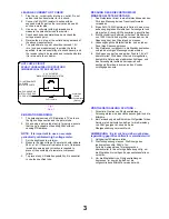
HOT CHECK CIRCUIT
a.c. VOLTMETER
Water Pipe
(Earth)
TO INSTRUMENT’S
EXPOSED
METALLIC PARTS
SCHALTUNGSAUFBAU FÜR PRUFUNG
IM EINGESCHALTETEN ZUSTAND
WECHSELSTROM-VOLTMETER
AN ZUGANGLICHE
METALLTEILE DAS
TV-GERATES
Wasserleitung
(Erdung)
Fig.1.
Abb.1.
2k
Ω
10 Watts
LEAKAGE CURRENT HOT CHECK
1. Plug the a.c. cord directly into the a.c. outlet. Do not
use an isolation transformer for this check.
2. Connect
a
2k
Ω
10W resistor in series with an
exposed metallic part on the receiver and an earth,
such as a water pipe.
3. Use an a.c. voltmeter with high impedance to
measure the potential across the resistor.
4. Check each exposed metallic part and check the
voltage at each point.
5. Reverse the a.c. plug at the outlet and repeat each of
the above measurements.
6. The potential at any point should not exceed 1,4V
rms. In case a measurement is outside the limits
specified, there is a possibility of a shock hazard, and
the receiver should be repaired and rechecked before
it is returned to the customer.
X-RADIATION WARNING
1. The potential sources of X-Radiation in TV sets are
the high voltage section and the picture tube.
2. When using a picture tube test jig for service, ensure
that the jig is capable of handling 29kV without
causing X-Radiation.
NOTE : It is important to use an accurate
periodically calibrated high voltage meter.
1. Set the brightness to minimum.
2. Measure the high voltage. The meter should indicate:
28kV ± 1kV. If the meter indication is out of tolerance,
immediate service and correction is required to
prevent the possibility of premature component
failure.
3. To prevent any X-Radiation possibility, it is essential
to use the specified tube.
MESSUNG DES KRIECHSTROMS IM
EINGESCHALTETEN ZUSTAND
1. Den Netzstecker direkt in eine Netsteckdose stecken.
Für diese Messung keinen Trenntransformator
verwenden.
2. Einen
2k
Ω
/ 10W-Widerstand in Serie mit einem von
außen zugänglichen Metallteil am Fernsehgerät und
einer guten, Erdung z.B Wasserleitung, anschließen.
3. Ein Wechselstrom-Voltmeter mit einem Meßbereich
von 1000 Ohm.Volt oder größer verwenden, um die
Spannung über den Widerstand zu messen.
4. Jedes zugängliche Metallteil prüfen, und an jedem
Punkt dies Spannung messen.
5. Den Netztecker umgekehrt in die Steckdose stecken
und jede der obigen Messungen wiederholen.
6. Die Spannung darf an keinem der Punkte 1,4V eff.
überschreiten. Wird dieser Wert nicht eingehalten,
besteht die Gefar eines elektrischen Schlages, und
das Fernsehgerät sollte daher repariert und
nachgeprüft werden, bevor es an den Kunden
zurückgegeben wird.
RÖNTGENSTRAHLUNG ACHTUNG
:
1. Potentielle Quellen von Röntgenstrahlung in
Fernsehgeräten sind das Hochspannungsteil und die
Bildröhre.
2. Bei Verwendung eines Bildröhren-Prüfgerätes für den
Service ist sicherzustellen, daß es für die Belastung
von 29kV geeignet ist, ohne daß eine
Röntgenstrahlung verursacht wird.
ANMERKUNG : Es ist wichtig, daß ein präzises,
regelmäßig geprüftes Voltmeter verwendet wird.
1. Helligkeit auf Minimum stellen.
2. Die Hochspannung messen. Die Anzeige des
Instrumentes sollte: 28kV ± 1kV.
Falls die Anziege diese Toleranzgrenzen
überschreitet, ist die sofortige Behebung nötig, um
die Möglichkeit vorzeitigen Komponentenausfalls zu
verhüten.
3. Um die Möglichkeit von Röntgenstrahlung zu
begrenzen, ist es wichtig, daß nur die
vorgeschriebene Bildröhre verwendet wird.
3
Содержание TX-28SL20F
Страница 25: ......
Страница 26: ......
Страница 27: ......
Страница 28: ......
Страница 29: ......
Страница 30: ......
Страница 33: ...N BOARD TNP8EN016 DIODES D1071 B3 D1072 A6 IC S IC1071 B2 C B A 1 2 3 4 5 6 7 8 29 ...
Страница 34: ...P BOARD TNP8EP017 DIODES D580 A3 D581 A3 A B C 30 5 4 3 2 1 ...
Страница 35: ...W BOARD TNP8EW002 I C S IC1901 A2 31 1 2 3 A C B ...


