


TH-50PV600AZ / TH-50PV600H / TH-50PV600M / TH-50PV600MT
A
WARNING
This service information is designed for experienced repair technicians only and is not designed for use by the general public.
It does not contain warnings or cautions to advise non-technical individuals of potential dangers in attempting to service a product.
Products powered by electricity should be serviced or repaired only by experienced professional technicians. Any attempt to service
or repair the product or products dealt with in this service information by anyone else could result in serious injury or death.
CONTENTS
Page
1 Applicable signals.............................................................................. 5
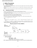
2 Safety Precautions............................................................................. 6
2.1. General Guidelines.................................................................. 6
2.2. Touch-Current Check.............................................................. 6
3 Prevention of Electro Static Discharge (ESD) to
Electrostatically Sensitive (ES) Devices....................................... 7
4 About lead free solder (PbF)............................................................8
5 Service H int..........................................................................................9
6 Plasma panel replacement method..............................................10
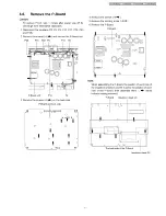
6.1. Remove the Back cover....................................................10
6.2. Remove the fan................................................................. 10
6.3. Remove the Speaker box ass’y (left)..............................10
6.4. Remove the Speaker box ass’y (right)........................... 10
6.5. Remove the rear terminal cover...................................... 10
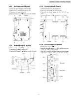
6.6. Remove the P-Board......................................................... 11
6.7. Remove the PA-Board...................................................... 12
6.8. Remove the tuner unit...................................................... 12
6.9. Remove the DG-Board..................................................... 12
6.10. Remove the TA-Board........................................................ 12
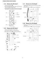
6.11. Remove the H-Board...........................................................13
6.12. Remove the HC-Board........................................................13
6.13. Remove the D-Board...........................................................13
6.14. Remove the SU-Board........................................................13
6.15. Remove the SD-Board........................................................14
6.16. Remove the SC-Board........................................................14
6.17. Remove the SS2-Board......................................................14
6.18. Remove the SS3-Board......................................................14
6.19. Remove the SS-Board........................................................ 15
6.20. Remove the C1-Board........................................................ 15
6.21. Remove the C2-Board........................................................ 15
6.22. Remove the C3-Board........................................................ 15
6.23. Remove the stand brackets............................................... 16
6.24. Remove the C4-Board........................................................ 16
6.25. Remove the C5-Board........................................................ 16
6.26. Remove the C6-Board........................................................ 16
6.27. Remove the front bracket................................................... 17
6.28. Remove the G-Board, GK-Board and GS-Board............ 17
6.29. Remove the S-Board...........................................................17
6.30. Remove the GS-Board and SD-Module........................... 17
6.31. Remove the Plasma panel section from the Front frame
(glass)...................................................................................... 18
6.32. Remove the squawker speaker......................................... 19
6.33. Remove the K-Board...........................................................19
6.34. Replace the plasma panel (finished)................................ 20
7 Location of Lead W iring..................................................................21
7.1. Lead of Wiring (1 )................................................................. 21
3
Page
7.2. Lead of Wiring (2 ).................................................................. 22
7.3. Lead of Wiring (3 ).................................................................. 23
7.4. Lead of Wiring (4 ).................................................................. 24
7.5. Lead of Wiring (5 ).................................................................. 25
8 Self-check Function......................................................................... 26
8.1. Power LED Blinking timing chart..........................................27
8.2. No Power.................................................................................28
8.3. No Picture................................................................................29
8.4. Local screen failure................................................................ 30
9 Service Mode Function.................................................................... 31
9.1. Howto enter SERVICE 1 ..................................................... 31
9.2. How to enter SERVICE 2 ..................................................... 31
9.3. Option Description.................................................................. 33
10 Adjustment Procedure.....................................................................35
10.1. Driver Set-up........................................................................... 35
10.2. Initialization Pulse Adjust.......................................................36
10.3. P.C.B. (Printed Circuit Board) exchange.............................36
10.4. Adjustment Volume Location................................................ 37
10.5. Test Point Location................................................................ 37
11 Adjustment......................................................................................... 38
11.1. PAL panel white balance adjustment.................................. 38
11.2. HD white balance adjustment...............................................39
11.3. Sub bright adjustment............................................................40
11.4. ABL adjustment.......................................................................41
11.5. Sub-Contrast adjustment.......................................................42
11.6. Multi-window adjustment....................................................... 43
12 Hotel m ode......................................................................................... 44
13 Conductor V iew s.............................................................................. 45
13.1. P-Board....................................................................................45
13.2. PA-Board................................................................................. 48
13.3. H, HC and TA-Board..............................................................50
13.4. G-Board................................................................................... 52
13.5. GK, K and S-Board................................................................ 53
13.6. DG-Board.................................................................................54
13.7. D-Board....................................................................................56
13.8. C1-Board................................................................................. 58
13.9. C2-Board................................................................................. 59
13.10. C3-Board................................................................................. 60
13.11. C4-Board.................................................................................. 61
13.12. C5-Board................................................................................. 62
13.13. C6-Board................................................................................. 63
13.14. SC-Board................................................................................. 64
13.15. SU-Board................................................................................. 67
13.16. SD-Board................................................................................. 68
13.17. SS-Board................................................................................. 69
13.18. SS-Board..................................................................................71
Содержание TH-50PV600AZ
Страница 21: ...TH 50PV600AZ TH 50PV600H TH 50PV600M TH 50PV600MT 7 Location of Lead Wiring 7 1 Lead of Wiring 1 21 ...
Страница 22: ... TH 50PV600AZ TH 50PV600H TH 50PV600M TH 50PV600MT 7 2 Lead of Wiring 2 22 ...
Страница 23: ...I TH 50PV600AZ TH 50PV600H TH 50PV600M TH 50PV600MTI 7 3 Lead of Wiring 3 23 ...
Страница 24: ...I TH 50PV600AZ TH 50PV600H TH 50PV600M TH 50PV600MTI 7 4 Lead of Wiring 4 24 ...
Страница 25: ...I TH 50PV600AZ TH 50PV600H TH 50PV600M TH 50PV600MTI 7 5 Lead of Wiring 5 25 ...
Страница 29: ...I TH 50PV600AZ TH 50PV600H TH 50PV600M TH 50PV600MTI 8 3 No Picture 29 ...
Страница 32: ...TH 50PV600AZ TH 50PV600H TH 50PV600M TH 50PV600M T 32 ...
Страница 84: ...ITH 50PV600AZ TH 50PV600H TH 50PV600M TH 50PV600MTI 14 5 P Board 2 of 2 Schematic Diagram 77 ...
Страница 94: ...TH 50PV600AZ H M MT G GK К and HC Board Block Diagram ...
Страница 100: ...ITH 50PV600AZ TH 50PV600H TH 50PV600M TH 50PV600MT 14 20 DG Board 1 of 8 Schematic Diagram A B C D E F i 2 3 4 5 92 ...
Страница 101: ... t H 50PV600AZ TH 50PV600H TH 50PV600M TH 50PV600MT 14 21 DG Board 2 of 8 Schematic Diagram 93 ...
Страница 102: ...ITH 50PV600AZ TH 50PV600H TH 50PV600M TH 50PV600MT 14 22 DG Board 3 of 8 Schematic Diagram 94 ...
Страница 103: ...ITH 50PV600AZ TH 50PV600H TH 50PV600M TH 50PV600MTI 14 23 DG Board 4 of 8 Schematic Diagram 95 ...
Страница 104: ...ITH 50PV600AZ TH 50PV600H TH 50PV600M TH 50PV600MT 14 24 DG Board 5 of 8 Schematic Diagram 96 ...
Страница 138: ...ITH 50PV600AZ TH 50PV600H TH 50PV600M TH 50PV600MT 14 56 SC Board 1 of 2 Schematic Diagram 128 ...
Страница 146: ...ITH 50PV600AZ TH 50PV600H TH 50PV600M TH 50PV600MTI 136 ...
Страница 147: ...ITH 50PV600AZ TH 50PV600H TH 50PV600M TH 50PV600MTI 15 3 Packing Exploded Views 2 137 ...
Страница 148: ...ITH 50PV600AZ TH 50PV600H TH 50PV600M TH 50PV600MTI 15 4 Packing Exploded Views 138 ...


