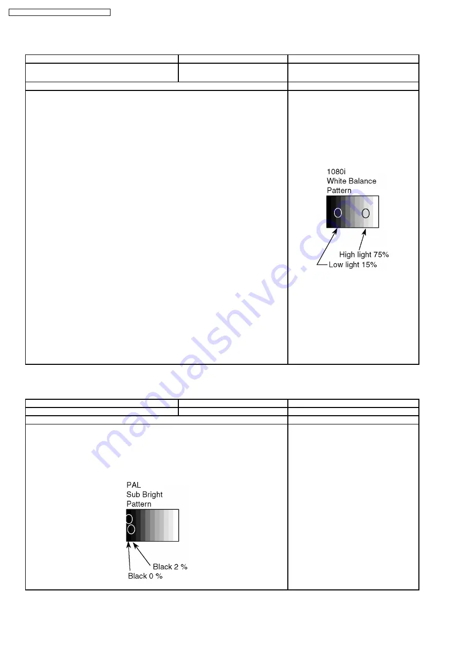
11.2. 1080i white balance adjustment
Instrument Name
Connection
Remarks
·
·
·
·
1080i W/B pattern
·
·
·
·
Color analyzer (Minolta CA-100 or equivalent)
Comonent terminal
Panel surface
User setting: Normal
Procedure
Remarks
·
·
·
·
Ensure aging is adequate (Longer than 15min.)
·
·
·
·
Make sure the front panel to be used on the final set is fitted.
·
·
·
·
Make sure a color signal is not being shown before adjustment.
·
·
·
·
Put the color analyzer where there is little color variation.
1.
Display the white balance pattern.
2.
Check that the color balance is "cool".
3.
Enter the "Service-Menu1" mode.
4.
Select "G-CUTOFF" item, using the color-key "Red" or "Green", and set to "128", using the
color-key "Yellow" or "Blue".
Also, "B-CUTOFF" and "R-CUTOFF" set to "128"
5.
Set "G-DRIVE" at "208".
6.
Touch the signal receiver of color analyzer to the highlight window´s center, and adjust B
drive and R drive so x, y become the "Color balance Cool" in the below table.
7.
Set "ALL-DRIVE" to "252".
8.
Set colorbalance to "Normal".
9.
Fix G cutoff , B cutoff and R cutoff at "128".
10. Fix G drive at "208".
11. Adjust B drive and R drive so the highlight window´s x, y become the "Color balance
"Normal" in the below table.
12. Set "ALL-DRIVE" to "252".
13. Set color balance to "Warm".
14. Set G cutoff, B cutoff and R cutoff to "128".
15. Set G drive to "208".
16. Adjust B drive and R drive so the highlight window´s x, y become the "Color balance Warm"
shown in the below table.
17. Set "ALL-DRIVE" to "252".
Picture menu: Dynamic
ASPECT:16:9
·
·
·
·
Highlight section
Signal amplitude 75%
* The Color balance COOL differs from
Japanese model values.
11.3. Sub bright adjustment
Instrument Name
Connection
Remarks
1.
PAL signal generator (or RF)
Connect to the input terminal
User setting: Normal
Procedure
Remarks
·
·
·
·
Color balance adjustment is finished for each signal.
·
·
·
·
Do adjustments in a dark room.
1.
Display the pattern for adjusting subbright from video input.
2.
Use "Sub-Bright" in the “Service-Menu1” mode to adjuct so the top part of the step section
in the below diagram faintly shows up and the middle fades away.
Picture menu: Dynamic
Color balance: Normal
ASPECT: 16:9
* If using RF ch.E04,
(Sub-Bright test pattern),
adjust so the 6th section shows up and the 7th
fades away.
40
TH-50PV500A / TH-50PV500H / TH-50PV500M
Содержание TH-50PV500A
Страница 5: ...1 Applicable signals 5 TH 50PV500A TH 50PV500H TH 50PV500M ...
Страница 29: ...8 3 No Picture 29 TH 50PV500A TH 50PV500H TH 50PV500M ...
Страница 32: ...32 TH 50PV500A TH 50PV500H TH 50PV500M ...
Страница 33: ...9 3 Option Description 33 TH 50PV500A TH 50PV500H TH 50PV500M ...
Страница 34: ...34 TH 50PV500A TH 50PV500H TH 50PV500M ...
Страница 35: ...9 4 Option Code 35 TH 50PV500A TH 50PV500H TH 50PV500M ...
Страница 44: ...44 TH 50PV500A TH 50PV500H TH 50PV500M ...
Страница 76: ...TH 50PV500A TH 50PV500H TH 50PV500M 76 ...
Страница 77: ...14 Block and Schematic Diagram 14 1 Schematic Diagram Notes TH 50PV500A TH 50PV500H TH 50PV500M 77 ...
Страница 140: ...TH 50PV500A TH 50PV500H TH 50PV500M 140 ...
Страница 141: ...15 Parts Location Mechanical Replacement Parts List 15 1 Parts Location 141 TH 50PV500A TH 50PV500H TH 50PV500M ...
Страница 142: ...15 2 Packing Exploded Views 1 142 TH 50PV500A TH 50PV500H TH 50PV500M ...
Страница 143: ...15 3 Packing Exploded Views 2 143 TH 50PV500A TH 50PV500H TH 50PV500M ...
Страница 144: ...15 4 Packing Exploded Views 3 144 TH 50PV500A TH 50PV500H TH 50PV500M ...
Страница 147: ...16 Electrical Replacement Parts List 16 1 Replacement Parts List Notes 147 TH 50PV500A TH 50PV500H TH 50PV500M ...
Страница 177: ...Ref No Part No Part Name Description Pcs Remarks 177 TH 50PV500A TH 50PV500H TH 50PV500M ...


