19
English
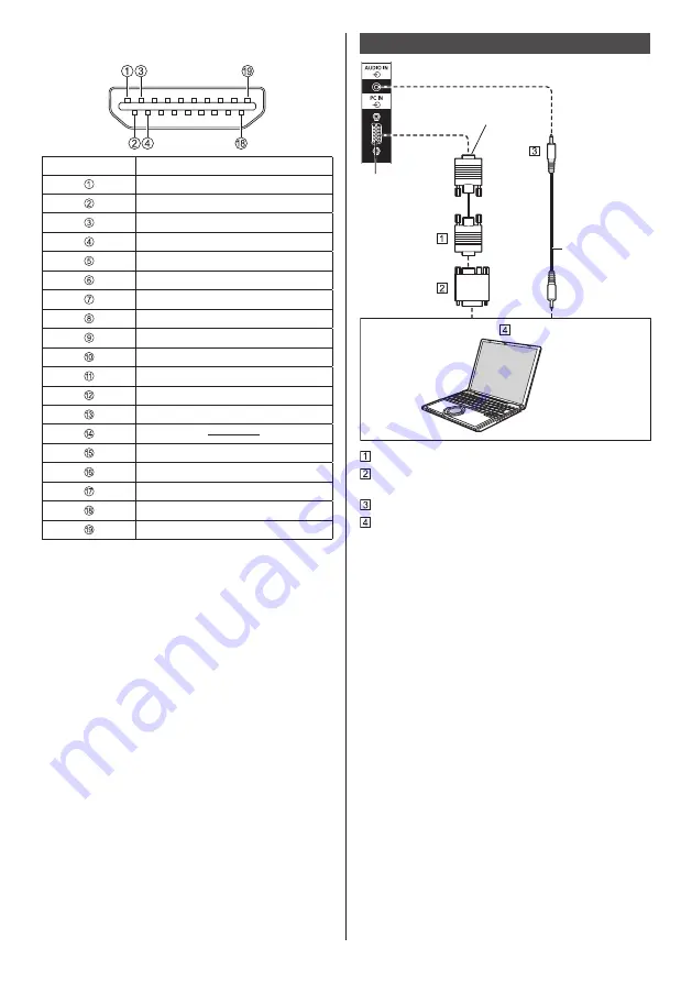
Pin assignments and signal names for HDMI
Terminal
Pin No.
Signal name
T.M.D.S Data2 +
T.M.D.S Data2 Shield
T.M.D.S Data2 -
T.M.D.S Data1 +
T.M.D.S Data1 Shield
T.M.D.S Data1 -
T.M.D.S Data0 +
T.M.D.S Data0 Shield
T.M.D.S Data0 -
T.M.D.S Clock +
T.M.D.S Clock Shield
T.M.D.S Clock -
CEC
SCL
SDA
DDC/CEC Ground
+5 V DC
Hot Plug Detect
PC IN terminal connection
Connect a cable
which matches
the audio output
terminal on the
computer.
(commercially
available)
(Female)
(Male)
Mini D-sub 15p cable (commercially available)
Conversion adapter (if necessary) (commercially
available)
Stereo mini plug (M3) cable (commercially available)
PC
The type of computer signal that can be connected
●
With regard to the typical PC input signals that
are described in “Preset Signals” (see page 52),
adjustment values such as for the standard picture
positions and sizes have already been stored in this
unit.
(Computer signals which can be input are those with
a horizontal scanning frequency of 31 to 83 kHz and
vertical scanning frequency of 56 to 76 Hz.)
●
If signals outside the range of supported frequencies
are input, normal images cannot be displayed. Note
that some images may not be correctly displayed
even if signals are within the range.
●
If the PC screen is not displayed, check if the image
signal of the PC meets “Preset Signals” (see page
52), and then change the settings. For power-saving
purpose, image output may be OFF on a notebook
computer. In this case, it may be set to ON with
function key operation etc. of the computer. (Refer to
the manual of the computer.)


