background image

12

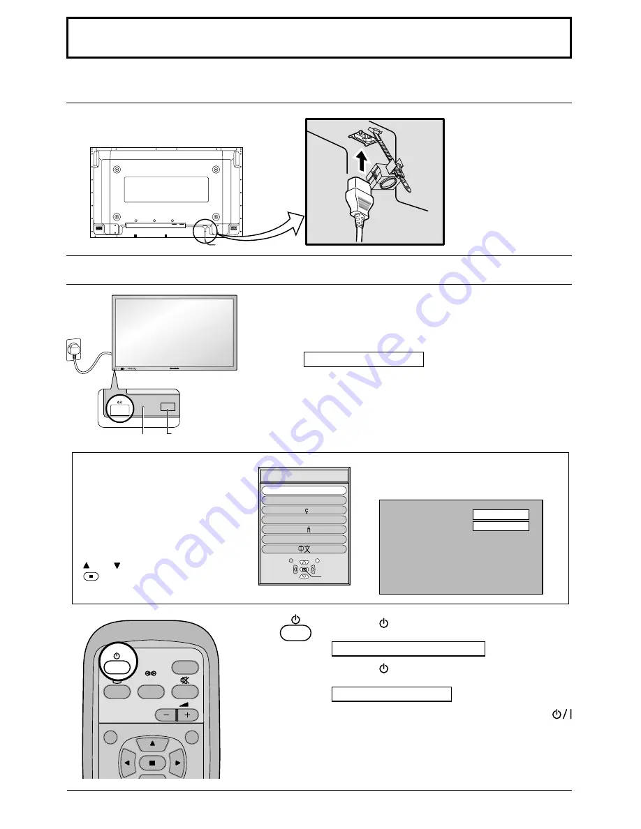
Plasma Display On/Off and input signal selection

Plasma Display On/Off

Remote Control Sensor

Power Indicator

Mains lead connection

When the Power is turned on for the first
time, the Language selection screen is
displayed.

From the second time on, language
selection can be done from the setup
menu. (see page 13)

Select the desired language using the

 and   keys and press the ACTION

 button.

From the second time on, the below screen
is displayed for a while (setting condition is
an example).

Press the 

 button on the remote control to turn the

Plasma Display to standby.

Power Indicator: Red (standby)

Press the 

 button on the remote control to turn the

Plasma Display on.

Power Indicator: Green

Turn the Plasma Display set off by pressing the 
switch on the Plasma Display, while it is on or in standby
mode.

Connecting the mains plug to the Plasma Display.

Note: During operation of the power management function, the power

indicator turns orange in the power off state.

Fix the mains plug
securely to the Plasma
Display with the clamper.
(see page 7)

Select

OSD  Language

Set

En

g

lish (UK)

Deutsch

Fran  ais

Italiano

Es

p

a  ol

ENGLISH (US)

INPUT

SURROUND

VOL

N

R

P C

4 : 3

R - STANDBY

G   POWER ON

R - STANDBY
G   POWER ON

TH-42PWD6

INPUT

MENU

ENTER

+

VOL

Connect the mains plug to the mains Outlet

Press the On/Off switch on the Plasma Display to turn the set
on: Power-On.

Power Indicator: Green

Example: The screen below is displayed for a while after the

Plasma Display is turned on. (setting condition is an
example.)

Содержание TH-42PHD6BX

Страница 1: ...ore connecting operating or adjusting this product please read these instructions completely Please keep this manual for future reference English Operating Instructions Progressive Wide Plasma Display TH 42PWD6 Model No High Definition Plasma Display TH 42PHD6 TH 50PHD6 Model No ...

Страница 2: ...venting after images 24 Setup of Screensaver Time 25 Reducing screen after image 25 Side Panel Adjustment 26 Reducing power consumption 27 Customizing the Input labels 27 Setup for MULTI DISPLAY 28 How to Setup MULTI DISPLAY 28 How to set the display location number for each Plasma Display 29 Setup for Input Signals 30 Component RGB in select 30 3D Y C Filter 30 Colour system Panasonic Auto 31 Cin...

Страница 3: ... A 5 amp fuse is fitted in this plug Shall the fuse need to be replaced please ensure that the replacement fuse has a rating of 5 amps and that it is approved by ASTA or BSI to BS1362 Check for the ASTA mark ASA or the BSI mark on the body of the fuse If the plug contains a removable fuse cover you must ensure that it is refitted when the fuse is replaced If you lose the fuse cover the plug must n...

Страница 4: ... using some other setting up method leave a space of at least 10 cm at the top bottom left and right and at least 1 9 cm at the rear Avoid installing this product near electronic equipment to avoid interference It will cause interference in image sound etc In particular keep video equipment away from this product When using the Plasma Display The Plasma Display is designed to operate on 220 240 V ...

Страница 5: ...iates infrared rays therefore it may affect other infrared communication equipment Install your infrared sensor in a place away from direct or reflected light from your Plasma Display Cleaning and maintenance The front of the display panel has been specially treated Wipe the panel surface gently using only a cleaning cloth or a soft lint free cloth If the surface is particularly dirty wipe with a ...

Страница 6: ...ng precaution Remote Control Batteries Two R6 size 1 Batteries shall always be replaced as a pair Always use new batteries when replacing the old set 2 Do not combine a used battery with a new one 3 Do not mix battery types example Zinc Carbon with Alkaline 4 Do not attempt to charge short circuit disassemble heat or burn used batteries 5 Battery replacement is necessary when remote control acts s...

Страница 7: ...d end through the locking block as shown in the figure While ensuring there is sufficient slack in cables to minimize stress especially in the power cord firmly bind all cables with the supplied fixing band From EXTERNAL monitor terminal on Computer see page 8 Mains lead connection see page 12 Optional Terminal Board insert Slots covered From SERIAL terminal on Computer To tighten To loosen Pull P...

Страница 8: ...e illustration is for example purposes only 7 Additional equipment and cables shown are not supplied with this set 8 Do not set the horizontal and vertical scanning frequencies for PC signals which are above or below the specified frequency range 9 Component Input is possible with the pin 1 2 3 of the D sub 15P Connector 1 6 7 8 3 9 4 5 10 15 14 13 12 11 2 Pin References for D sub 15P Connector Pi...

Страница 9: ...ultiple commands are transmitted be sure to wait for the response for the first command to come from this unit before sending the next command 2 If an incorrect command is sent by mistake this unit will send an ER401 command back to the computer Pin layout for RS 232C 9 8 7 6 5 3 2 1 4 Communication parameters Signal level Synchronization method Baud rate Parity Character length Stop bit Flow cont...

Страница 10: ...e page 17 18 19 20 Press the Status button to display the current system status Off timer 90 2 3 1 PC 4 3 Normal Viewing Picture Set up Sound Picture Pos Size PICTURE button see page 18 MULTI PIP Each time pressing this button main picture and sub picture will be displayed as follows bellow Press to swap main picture and sub picture Picture out Picture Press the SELECT button Under main Picture an...

Страница 11: ...nput mode This button is used to switch directly to PC input mode INPUT button INPUT1 INPUT2 INPUT3 and PC IN Selection Press to select INPUT1 INPUT2 INPUT3 and PC IN input SLOTS sequentially see page 13 Sound mute On Off see page 20 Volume Adjustment Press the Volume Up or Down button to increase or decrease the sound volume level ACTION button Press to make selections ASPECT button Press to adju...

Страница 12: ...n the Plasma Display on Power Indicator Green Turn the Plasma Display set off by pressing the switch on the Plasma Display while it is on or in standby mode Connecting the mains plug to the Plasma Display Note During operation of the power management function the power indicator turns orange in the power off state Fix the mains plug securely to the Plasma Display with the clamper see page 7 Select...

Страница 13: ...ptional Terminal Boards Notes 1 Input terminal will not be selected if the terminal board is not installed into the SLOT 2 Select to match the signals from the source connected to the component RGB input terminals see page 30 3 In 2 screen display the same input mode cannot be selected for the main picture and sub picture Input signals will change as follows R STANDBY G POWER ON INPUT MENU ENTER V...

Страница 14: ... extension W B High R W B High B 0 0 0 0 Input level 0 0 W B Low R Gamma 2 2 AGC Off 0 W B Low B Press to enter Advanced settings Press to select On Picture Normalise Picture Mode Brightness Colour Normal 0 0 Tint White balance Normal Advanced settings On Contrast 25 0 0 Sharpness Normal To Picture adjust menu see page 18 The MENU button on the unit can also be pressed Each time the MENU button is...

Страница 15: ...Start Time 7 00 8 00 Side panel High Wobbling Off Peak limit Off Finish Time Start PRESENT TIME 10 00 MULTI DISPLAY Setup MULTI DISPLAY Setup Ratio On 2 2 Location A1 Screensaver Function Mode White bar scroll Interval Periodic Time 1 00 0 15 Side panel High Wobbling Off Peak limit Off Operating Time Start PRESENT TIME 10 00 Screensaver Function Mode White bar scroll Interval Periodic Time 0 00 0 ...

Страница 16: ...l depend on the original signal Picture The display will automatically become enlarged depending on the picture source allowing you to view the picture at its maximum size Note Panasonic Auto mode is designed to automatically adjust the aspect ratio to handle a mix of 16 9 and 4 3 program material Certain 4 3 program material such as stock market data screens may occasionally cause the image size ...

Страница 17: ... are returned to the factory settings N Clock Phase RGB PC in Mode When the Position Left button is pressed When the Position Left button is pressed When the Position Left button is pressed When the Position Left button is pressed When the Position Right button is pressed When the Position Right button is pressed When the Position Right button is pressed When the Position Right button is pressed N...

Страница 18: ...ts This menu selects the normal levels of Brightness and Contrast Dynamic For viewing in brighter environments This menu selects higher than normal levels of Brightness and Contrast Cinema Ideal for movies Auto Automatically selects the mode that best suits the brightness of the environment Advanced settings On Enables fine picture adjustment at a professional level see next page Advanced settings...

Страница 19: ...ess Colour Tint Sharpness for each Picture menu 3 The setting details for normal dynamic and cinema respectively are memorized separately for each input mode INPUT1 INPUT2 INPUT3 and PC IN 4 The Tint setting can be adjusted for NTSC signal only during AV S Video input signal Less More Less More Item Black extension Input level W B High R W B High B W B Low R W B Low B Gamma AGC Helpful Hint Normal...

Страница 20: ...lise Normalisation N To end adjustments Note Press the SURROUND button to directly turn the surround effect On and Off see page 11 Bass Treble and Surround settings are memorized separately for each Sound mode Normal Auto 2 Select to adjust each item Press to select the desired adjustment menu Select the desired level by listening to the sound Bass Adjusts low sounds Treble Adjusts high sounds Bal...

Страница 21: ...T MENU ENTER VOL TH 42PWD6 1 Exit R N R MULTI PIP SWAP SELECT MOVE INPUT VOL PICTURE SOUND SET UP ASPECT PICTURE POS SIZE OFF TIMER PC SURROUND ZOOM Notes 1 When power goes OFF including Off Timer operation Digital Zoom terminates 2 The Digital Zoom function cannot be selected while in the following operation states Multi screen MULTI DISPLAY see page 28 Multi viewer Picture in Picture Picture out...

Страница 22: ...Set Press to store PRESENT TIME Setup Press to set up PRESENT TIME button Forward button Back Notes Pressing or button once changes PRESENT TIME 1minute Pressing or button continuously changes PRESENT TIME by 15 minutes Note Set cannot be selected unless PRESENT TIME is set SET UP INPUT SURROUND VOL N PICTURE SOUND R MULTI SET UP ZOOM Press to exit from PRESENT TIME Setup Setup 1 2 Signal Screensa...

Страница 23: ...e Timer function will not work unless PRESENT TIME is set Notes Pressing or button once changes POWER ON Time POWER OFF Time 1minute Pressing or button continuously changes POWER ON Time POWER OFF Time by 15 minutes Display the Set up TIMER screen R Set up TIMER POWER ON Function Off POWER ON Time POWER OFF Function POWER OFF Time 0 00 0 00 Off 2 30 PRESENT TIME Set up TIMER POWER ON Function On P...

Страница 24: ...ting Time are setup and those times arrive Off White bar scroll Image Reversal On Operates when Start is selected and the ACTION is pressed Start setting 5 When the Mode is set to On press to select Start Press to start Screensaver The menu screen will disappear and the Screensaver will be activated To stop the Screensaver under On press the R button Screensaver Function Mode White bar scroll Off ...

Страница 25: ...Side panel High Wobbling Off Operating Time Start PRESENT TIME 10 00 Screensaver Function Mode White bar scroll Side panel High Wobbling Off Time Designation Start Time 0 00 0 00 Finish Time Start PRESENT TIME 10 00 Screensaver Function Mode White bar scroll Side panel High Wobbling Off Interval Periodic Time 0 00 0 00 Operating Time Start PRESENT TIME 10 00 Screensaver Function Mode White bar scr...

Страница 26: ...ps 1 and 2 Notes Setting the side panel to High mode for an extended period may result in occurrence of after images The side panels may flash alternate black white depending on the picture being shown on the screen In such an occurrence use the Cinema mode Off Low Mid High R Screensaver Function Mode White bar scroll Time Designation Start Time 0 00 0 00 Side panel High Wobbling Off Peak limit Of...

Страница 27: ...etup Press to select Input label Press to change the Input label Customizing the Input labels This function can change the label of the Input signal to be displayed Notes While selecting an Input signal through Optional Terminal Board connected to Slot1 to Slot3 the Input label will depend on each Optional Terminal Board Input labels for Slot1 to Slot3 and miniD sub Slot1 Input INPUT1 VIDEO1 COMPO...

Страница 28: ...Y Setup menu Press to select the MULTI DISPLAY Setup 1 2 3 Press to select the MULTI DISPLAY Setup Press to select On or Off How to Setup MULTI DISPLAY group of 4 2 2 group of 9 3 3 INPUT SURROUND VOL N PICTURE SOUND R MULTI SET UP ZOOM SET UP MULTI DISPLAY Setup MULTI DISPLAY Setup Ratio On 2 2 Location A1 Setup 1 2 Signal Screensaver Input label Component RGB in select RGB RGB1 OSD Language Engl...

Страница 29: ...ISPLAY Setup MULTI DISPLAY Setup Ratio On 2 2 Location A1 MULTI DISPLAY Setup MULTI DISPLAY Setup Ratio On 2 2 Location A1 R A1 A2 B1 B2 A1 A2 A3 B1 B2 B3 C1 C2 C3 Notes 1 For RGB PC input signals normal multi display magnification is only available at the VGA SVGA and XGA resolution 2 The multi display capability is functional for the following component signals 525 480 60i 60p 625 575 50i 50p 11...

Страница 30: ...o input signal Signal AV menu is displayed Press to select the 3D Y C Filter NTSC Press to set On Off Press to exit from adjust mode Note When On this setting only affects NTSC input signals INPUT SURROUND VOL N R PICTURE SOUND SET UP MULTI PIP SWAP SELECT MOVE ZOOM SET UP R Press ACTION button Component RGB R Setup 1 2 Signal Screensaver Input label Component RGB in select RGB RGB1 OSD Language E...

Страница 31: ...V Auto PAL SECAM M NTSC NTSC Setup 1 2 Signal Screensaver Input label Component RGB in select RGB RGB1 OSD Language English UK Power save Off Standby save On Power management Off Cinema reality Select Signal from the Setup menu during AV S Video or Component input signal Signal AV or Signal Component menu is displayed Press to select Cinema reality Press to set On Off Press to exit from adjust mod...

Страница 32: ...display is valid only for RGB PC and DVI input signal Display range Horizontal 15 110 kHz Vertical 48 120 Hz H Freq kHz V Freq Hz Setup for input signals Sync Press to exit from adjust mode Press ACTION button Sync H V Sync CS Sync on G H Freq kHz V Freq Hz 31 5 60 0 Signal RGB Sync H Freq kHz V Freq Hz H V 31 5 60 0 R Setup 1 2 Signal Screensaver Input label Component RGB in select RGB RGB1 OSD L...

Страница 33: ...own below This Plasma Display uses special image processing Hence a slight time lag may occur between image and audio depending on the type of input signal However this is not a malfunction Plasma Display panel Check The plasma display panel is manufactured using an extremely high level of precision technology however sometimes some parts of the screen may be missing picture elements or have lumin...

Страница 34: ... 080 50i 31 25 50 00 12 640 400 70 Hz 31 47 70 00 13 640 480 60 Hz 31 47 59 94 14 Macintosh13 640 480 35 00 66 67 15 640 480 75 Hz 37 50 75 00 16 852 480 60 Hz 31 50 60 00 17 800 600 60 Hz 37 88 60 32 18 800 600 75 Hz 46 88 75 00 19 800 600 85 Hz 53 67 85 06 20 Macintosh16 832 624 49 73 74 55 21 1 024 768 60 Hz 48 36 60 00 22 1 024 768 70 Hz 56 48 70 07 23 1 024 768 75 Hz 60 02 75 03 24 1 024 768 ...

Страница 35: ...mm H 1 056 mm diagonal 1 056 mm diagonal 1 269 mm diagonal 408 960 852 W 480 H 786 432 1 024 W 768 H 1 049 088 1 366 W 768 H 2 556 480 dots 3 072 768 dots 4 098 768 dots 0 C 40 C 20 80 NTSC PAL PAL60 SECAM Modified NTSC 525 480 60i 60p 625 575 50i 50p 750 720 60p 50p 1125 1080 60i 50i 24p 24sF SMPTE274M 1250 1080 50i VGA display XGA display VGA VGA SVGA XGA SVGA XGA SXGA UXGA SXGA UXGA compressed ...

Страница 36: ...in the space provided below and retain this book plus your purchase receipt as a permanent record of your purchase to aid in identification in the event of theft or loss and for Warranty Service purposes Model Number Serial Number Matsushita Electric Industrial Co Ltd Web Site http www panasonic co jp global Printed in Japan MBS0703S0 ...

Отзывы: