background image

25

PICTURE Adjustments

ADVANCED SETTINGS

Notes:

•  “COLOR” and “TINT” settings cannot be 

adjusted for “RGB/PC” input signal.

•  You can change the level of each function 

(PICTURE, BRIGHTNESS, COLOR, TINT, 
SHARPNESS) for each PICTURE MENU.

• The setting details for STANDARD, 

DYNAMIC and CINEMA respectively 
are memorized separately for each input 
terminal.

• The “TINT” setting can be adjusted 

for NTSC signal only during “VIDEO 
(S VIDEO)” input signal.

• In PICTURE, there is not a noticeable 

change even when contrast is increased 
with a bright picture or reduced with a dark 
picture.

On the remote control unit, while the “ADVANCED SETTINGS” menu is displayed, if either the N button is pressed at any time 
or the ACTION (  ) button is pressed during “NORMALIZE”, then all adjustment values are returned to the factory settings.

Helpful Hint (    / 

NORMALIZE

  Normalization)

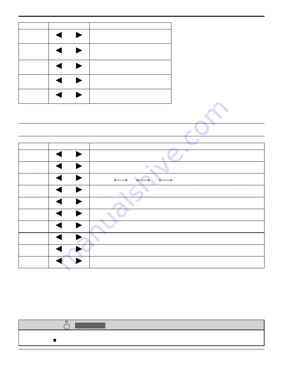
Item

Effect Adjustments

PICTURE

Less

More

Adjusts the proper picture contrast.

BRIGHTNESS

Darker

Brighter

Adjusts for easier viewing of dark 
pictures such as night scenes and 
black hair.

COLOR

Less

More

Adjusts color saturation.

TINT

Reddish

Greenish

Adjusts for natural 

fl

 esh tones.

SHARPNESS

Less

More

Adjusts picture sharpness.

Item

Effect Details

BLACK

EXTENSION

Less

More

Adjusts the dark shades of the image in gradation.

INPUT 

LEVEL

Less

More

Adjustment of parts which are extremely bright and hard to see.

GAMMA

Down

Up

S CURVE 

  2.0 

  2.2 

   2.5

AGC

OFF

ON

Increases the brightness of dark signal automatically.

W/B HIGH R

Less

More

Adjusts the white balance for light red areas.

W/B HIGH G

Less

More

Adjusts the white balance for light green areas.

W/B HIGH B

Less

More

Adjusts the white balance for light blue areas.

W/B LOW R

Less

More

Adjusts the white balance for dark red areas.

W/B LOW G

Less

More

Adjusts the white balance for dark green areas.

W/B LOW B

Less

More

Adjusts the white balance for dark blue areas.

Notes:

•  Carry out “W/B” adjustment as follows.

1.

 Adjust the white balance of the bright sections using the “W/B HIGH R” , “W/B HIGH G” and “W/B HIGH B” settings.

2.

 Adjust the white balance of the dark sections using the “W/B LOW R” , “W/B LOW G” and “W/B LOW B” settings.

3.

 Repeat steps 

1

 and 

2

 to adjust.

 Steps 

1

 and 

2

 affect each other’s settings, so repeat each step in turn to make the adjustment.

•  The adjustment values are memorized separately for each input terminal.
•  The adjustment range values should be used as an adjustment reference.

Содержание TH-42PD12U

Страница 1: ...usting this product please read these instructions completely Please keep this manual for future reference English The illustration shown is an image TH 42PD12U TH 50PD12U Model No Operating Instructi...

Страница 2: ...O NOT OPEN WARNING To prevent damage which may result in fire or shock hazard do not expose this apparatus to rain or moisture Do not place containers with water flower vase cups cosmetics etc above t...

Страница 3: ...nt of the obsolete outlet 10 Protect the power cord from being walked on or pinched particularly at plugs convenience receptacles and the point where they exit from the apparatus 11 Only use attachmen...

Страница 4: ...connection 12 Power ON OFF 13 Selecting the input signal 15 Basic Controls 16 ASPECT Controls 18 MULTI PIP 19 Digital Zoom 20 On Screen Menu Displays 21 Adjusting POS SIZE 22 PICTURE Adjustments 24 AD...

Страница 5: ...2 this device must accept any interference received including interference that may cause undesired operation FCC CAUTION To assure continued compliance follow the attached installation instructions...

Страница 6: ...the power cord plug can increase humidity which might damage the insulation and cause fire Unplug the cord from the wall outlet and clean it with a dry cloth This Plasma Display radiates infrared rays...

Страница 7: ...stal optional accessory leave a space of 3 15 16 10 cm or more at the top left and right and 2 3 4 7 cm or more at the rear and also keep the space between the bottom of the display and the floor surf...

Страница 8: ...arge short circuit disassemble heat or burn used batteries 5 Battery replacement is necessary when the remote control acts sporadically or stops operating the Plasma Display 6 Do not burn or breakup b...

Страница 9: ...able fixing band through the clip as shown in the figure To secure cables connected to Terminals wrap the cable fixing band around them then pass the pointed end through the locking block as shown in...

Страница 10: ...ters with DOS V compatible Mini D sub 15P terminal The computer shown in the illustration is for example purposes only Additional equipment and cables shown are not supplied with this set Do not set t...

Страница 11: ...arameter s 1 5 bytes End 03h STX C1 C2 C3 P1 P2 P3 P4 P5 ETX Notes If multiple commands are transmitted be sure to wait for the response for the first command to come from this unit before sending the...

Страница 12: ...SELECT setting in the SET UP menu to COMPONENT when COMPONENT signal connection or RGB when RGB signal connection see page 35 SYNC ON G signal is needed see page 39 VIDEO OUT AUDIO OUT RGBOUT YPB PR O...

Страница 13: ...ocket outlet first Press the Power switch on the Plasma Display to turn the set on Power On Power Indicator Green Press the button on the remote control to turn the Plasma Display off Power Indicator...

Страница 14: ...creen will be displayed when the unit is turned on for the first time Select the items with the remote control Unit buttons are invalid OSD LANGUAGE DISPLAY ORIENTATION 1 Select the language 2 Set 1 F...

Страница 15: ...e component RGB input terminals see page 35 In 2 screen display the same input mode cannot be selected for the main picture and sub picture Image retention image lag may occur on the plasma display pa...

Страница 16: ...ndicator not illuminated The unit will still consume some power as long as the power cord is still inserted into the wall outlet Standby Red Power ON Green DPMS POWER MANAGEMENT Orange With PC input s...

Страница 17: ...ital Zoom see page 20 Remote Control Transmitter AUTO SETUP button Automatically adjusts the position size of the screen see page 22 SET UP button see page 21 SOUND button see page 26 Volume Adjustmen...

Страница 18: ...nput terminal Do not allow the picture to be displayed in 4 3 mode for an extended period as this can cause a permanent image retention to remain on the Plasma Display Panel For SD signal input 525 48...

Страница 19: ...Main picture Sub picture Main picture Sub picture Normal Viewing MULTI PIP Notes If INPUT lock in Options menu is set to other than Off MULTI PIP function isn t available Sound output is from the pic...

Страница 20: ...Picture in Picture Picture out Picture Picture and Picture operation see page 19 When MULTI DISPLAY SETUP is ON see page 33 When SCREENSAVER except for NEGATIVE IMAGE is running see page 27 While Dig...

Страница 21: ...0 SOUND NORMAL NORMALIZE STANDARD TREBLE AUDIO MENU BALANCE BASS MAIN AUDIO OUT PIP EXPRESS SETTINGS CUSTOM SETTINGS RESET EXTENDED LIFE SETTINGS 21 On Screen Menu Displays Remote Control Unit 1 Displ...

Страница 22: ...down This picture position movement cannot be controlled by the POS SIZE function AUTO SETUP H POS V POS H SIZE V SIZE DOT CLOCK and CLOCK PHASE are automatically adjusted when the INPUT3 COMPONENT R...

Страница 23: ...F is set H SIZE and V SIZE cannot be adjusted When the Display size is set to On in the Options menu this setting will be invalid see page 41 Adjusting POS SIZE Notes If the dot clock frequency is 108...

Страница 24: ...to something else adjust using the items in the PICTURE menu see next page PICTURE Adjustments 1 ADVANCED SETTINGS ON Enables fine picture adjustment at a professional level see next page ADVANCED SET...

Страница 25: ...ts for natural flesh tones SHARPNESS Less More Adjusts picture sharpness Item Effect Details BLACK EXTENSION Less More Adjusts the dark shades of the image in gradation INPUT LEVEL Less More Adjustmen...

Страница 26: ...or the ACTION button is pressed during NORMALIZE then all adjustment values are returned to the factory settings Helpful Hint NORMALIZE Normalization 3 Item Details AUDIO MENU STANDARD Emits the origi...

Страница 27: ...each mode items SCREENSAVER For preventing image retention Setup of SCREENSAVER Time After selecting INTERVAL or STANDBY AFTER SCR SAVER the relevant Time Setup will become available for selection and...

Страница 28: ...d as this can cause an image retention to remain on the side bars on either side of the display field To reduce the risk of such an image retention illuminate the side bars This function may be applic...

Страница 29: ...NGS 1 select 2 set PICTURE MENU PICTURE EXTENDED LIFE SETTINGS DYNAMIC SIDE BAR ADJUST WOBBLING LOCK SETTINGS PEAK LIMIT BRIHGT OFF UNLOCK APPLY TO CURRENT INPUT APPLY TO ALL INPUTS OFF 30 RECOMMENDED...

Страница 30: ...When this function is set to ON it operates under the following conditions to turn the power on or off automatically When no pictures HD VD sync signals are detected for 30 or so seconds during PC si...

Страница 31: ...isplayed Select the input signal which you would like to change its label before customizing the Input labels see page 15 17 INPUT LABELS for INPUT1 2 3 and 4 INPUT1 VIDEO DVD1 DVD2 DVD3 Blu ray1 Blu...

Страница 32: ...l will be switched when turning on the unit next time LANDSCAPE PORTRAIT Fan control for horizontal installation Fan control for vertical installation On screen menu will be rotated 90 degrees counter...

Страница 33: ...ION OFF SEAM HIDES VIDEO 2 MULTI DISPLAY SETUP SET UP for MULTI DISPLAY Example group of 25 5 5 Press to display the SET UP menu 1 2 3 Press to select the MULTI DISPLAY SETUP Press to select ON or OFF...

Страница 34: ...mber button is pressed more than two times the first two numbers become the ID number for the remote control ID Cancellation Press button on remote control This has the same effect as pressing the but...

Страница 35: ...EQ V FREQ kHz Hz 63 98 60 02 SIGNAL FORMAT 1280 1024 60 RGB 3 2 PULLDOWN XGA MODE NOISE REDUCTION OFF REFRESH RATE 100 Hz AUTO OFF AUTO 35 SET UP for Input Signals COMPONENT RGB IN SELECT Select to ma...

Страница 36: ...VIDEO S VIDEO input signal mode SIGNAL VIDEO menu is displayed Press to select the COLOR SYSTEM Press to select each function If the image becomes unstable With the system set on Auto under condition...

Страница 37: ...signal input during COMPONENT input signal XGA MODE This menu displays when INPUT3 COMPONENT RGB and INPUT4 PC signals are selected This unit supports three types of XGA signals with 60Hz vertical fr...

Страница 38: ...is being applied REFRESH RATE SET UP for Input Signals Press to select REFRESH RATE Press to adjust This function sets the refresh rate of the display This menu is displayed when the input signal is 5...

Страница 39: ...al AUTO The H and V sync or synchronized signal are automatically selected If both input it is selected the H and V sync ON G Uses a synchronized signal on the Video G signal which is input from the G...

Страница 40: ...the unit is turned on Off On Off Sets normal volume On Sets your preferred volume Notes When Maximum VOL level is On the volume can only be adjusted between 0 and your maximum range You can hear the c...

Страница 41: ...mode of the unit for when the power recovers from failure or after plugging off and in again Normal Power returns in as the same state as before the power interruption Standby Power returns in standby...

Страница 42: ...d in again the power cord All Aspect Sets All Aspect mode advanced aspect setting or default aspect mode With each press of button the aspect changes in the selected mode Off Default aspect mode On Al...

Страница 43: ...Press to display the SET UP menu Press to select OSD LANGUAGE Press for more than 3 seconds Press to select Shipping Press to display the Shipping menu Press to select YES Press to confirm from the u...

Страница 44: ...between image and audio depending on the type of input signal However this is not a malfunction Plasma Display panel Symptoms Check The screen darkens slightly when bright pictures with minimal movem...

Страница 45: ...areas around the left and right edges of the screen is slightly elongated 4 3 4 3 Pictures with a 4 3 aspect ratio are displayed with their original aspect ratio Side panels are displayed at the left...

Страница 46: ...74 25 1 11 1 125 1 080 24sF 27 00 47 92 74 25 2 12 1 125 1 080 30p 33 75 30 00 74 25 1 13 1 125 1 080 25p 28 13 25 00 74 25 1 14 1 125 1 080 24p 27 00 24 00 74 25 1 15 1 250 1 080 50i 31 25 50 00 74 2...

Страница 47: ...VGA SVGA XGA SXGA UXGA compressed Horizontal scanning frequency 15 110 kHz Vertical scanning frequency 48 120 Hz Connection terminals VIDEO BNC 1 0 Vp p 75 S VIDEO MINI DIN 4PIN Y 1 0 Vp p 75 C 0 286...

Страница 48: ...0068 323 436 3500 Dallas Region 6226 Abington Way Houston TX 77008 713 802 2726 No CA Northwest Region 5870 Stone Ridge 3 Pleasanton CA 925 416 5108 Government Marketing Department 52 West Gude Drive...

Отзывы: