25
English
Identifying Controls
Main Unit
●
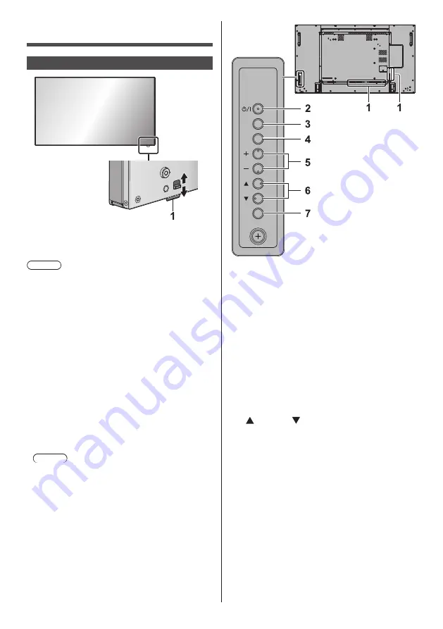
The power indicator and remote control sensor can
be pulled out by sliding the lever on the rear panel.
To store the part, press it directly.
Note
●
For normal use, pull out the power indicator and
remote control sensor from the edge side of the
main unit by operating the lever on the rear panel.
Depending on the setup condition such as when
using the multi display, store them in the main unit.
1 Power Indicator / Remote control sensor
The Power Indicator will light.
When the power of the unit is ON (Main Power On
/ Off button: ON)
●
Picture is displayed: Green
●
Power OFF (Standby) with remote control: Red
When [Network control] is set to [On] (see page
54): Orange (Red/Green)
●
Power OFF with “Power management” function
(see page 50): Orange (Red/Green)
When the power of the unit is OFF (Main Power
On / Off button: OFF): No light
Note
●
The unit will still consume some power as long as
the power cord is still inserted into the wall outlet.
●
When the power indicator is orange, power
consumption during standby is generally larger than
that of when the power indicator is red.
INPUT
MENU
ENTER
1 External Input Terminal
●
Connects to video equipment, PC, etc. (see page
14)
2 <Main Power On / Off button>
●
Turns the power On / Off.
3 <INPUT (Unit)> (INPUT signal selection)
●
Selects the connected device. (see page 29)
4 <MENU (Unit)>
●
Each time the <MENU (Unit)> button is pressed,
the menu screen will switch. (see page 33)
5 <+ (Unit)> / <- (Unit)>
●
Adjusts the volume. (see page 30)
●
On the main screen, switches settings or adjusts
settings level. (see page 33)
6 < (Unit)> / < (Unit)>
●
Selects the setting item. (see page 33)
7 <ENTER (Unit)>
●
Configures the item on menu screen. (see page
33)
●
Switches aspect mode. (see page 31)


