Panasonic TH-42LF30U Скачать руководство пользователя страница 22

22

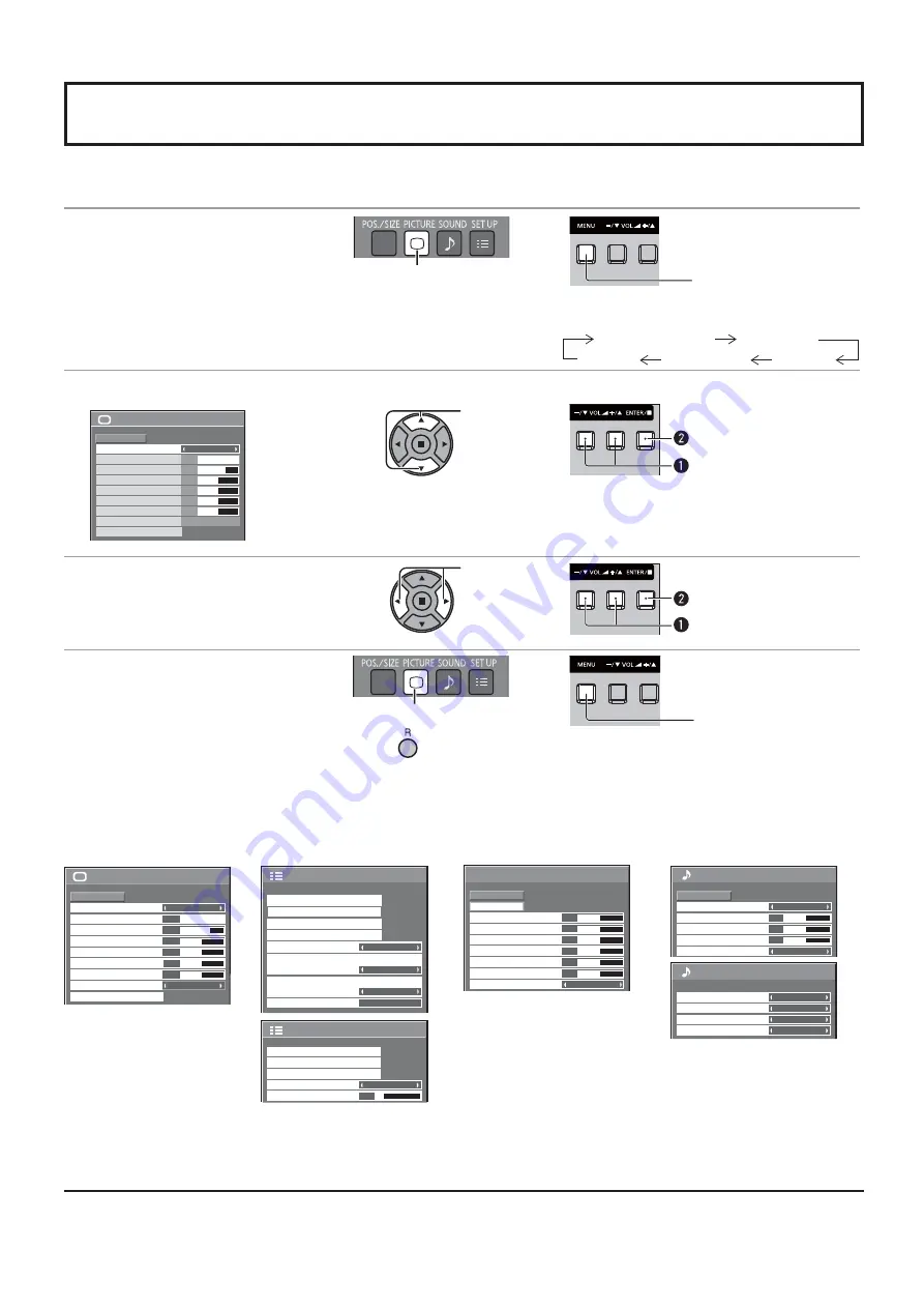
On-Screen Menu Displays

Remote Control

Unit

1

Display the menu screen.

Press to select.
(Example: PICTURE menu)


Press several times.

Each time the MENU button is pressed, the 
menu screen will switch.

Normal Viewing

PICTURE

SOUND

POS. /SIZE

SET UP

2

Select the item.


100

70
50
50
50

PICTURE 

NORMAL 

NORMALIZE 

STANDARD 

BRIGHTNESS

PICTURE MENU 

COLOR

PICTURE

BACKLIGHT

TINT

ADVANCED SETTINGS

COLOR TEMP

NORMAL

SHARPNESS

50

( Example: 

PICTURE menu)

Select.

 Press.

 Select.

3

Set.

Adjust.

 Press.

 Adjust.

4

Exit the menu.

Press.

Press 

 to return to the 

previous menu.


                                Press several times.

1/2

SIGNAL

INPUT LABEL

ECO MODE SETTINGS

WOBBLING

SET UP

OFF

COMPONENT/RGB-IN SELECT

RGB

SCREENSAVER

NO ACTIVITY POWER OFF

DISABLE

OSD LANGUAGE

ENGLISH (US)

2/2 

SET UP

MULTI DISPLAY SETUP

SET UP TIMER

PRESENT TIME SETUP

MENU DISPLAY DURATION

15 S

MENU TRANSPARENCY

20

PICTURE menu

SET UP menu

POS./SIZE menu

SOUND menu

Menu display list

Note:

 Menu that cannot be adjusted is grayout. Adjustable menu changes depending on signal, input and menu setting.

see page 25, 26

see page 28-42

see page 23, 24

see page 27

2/2

SOUND OUT

LEFT CHANNEL
RIGHT CHANNEL

CHANNEL 1
CHANNEL 1

OFF

LEVEL METER

OFF

SDI SOUND OUTPUT

100

70
50
50
50

PICTURE

NORMAL

NORMALIZE

STANDARD

BRIGHTNESS

PICTURE MENU

COLOR

PICTURE

BACKLIGHT

TINT

ADVANCED SETTINGS

COLOR TEMP

NORMAL

SHARPNESS

50

0

NORMAL 

NORMALIZE 

AUTO SETUP

POS. /SIZE 

V-POS

0

H-POS

V-SIZE
CLOCK PHASE

H-SIZE

1:1 PIXEL MODE

DOT CLOCK

0
0
0

0

OFF

0
0
0

SOUND 

NORMAL 

NORMALIZE 

STANDARD

OFF

TREBLE

AUDIO MENU 

BALANCE

BASS 

SURROUND

1/2

Содержание TH-42LF30U

Страница 1: ... TH 47LF30U Model No Operating Instructions FULL HD LCD Display English Before connecting operating or adjusting this product please read these instructions completely Please keep this manual for future reference ...

Страница 2: ...e or shock hazard do not expose this apparatus to rain or moisture Do not place containers with water Àower vase cups cosmetics etc above the set including on shelves above etc WARNING 1 To prevent electric shock do not remove cover No user serviceable parts inside Refer servicing to quali ed service personnel 2 Do not remove the grounding pin on the power plug This apparatus is equipped with a th...

Страница 3: ...ent of the obsolete outlet 10 Protect the power cord from being walked on or pinched particularly at plugs convenience receptacles and the point where they exit from the apparatus 11 Only use attachments accessories speci ed by the manufacturer 12 Use only with the cart stand tripod bracket or table speci ed by the manufacturer or sold with the apparatus When a cart is used use caution when moving...

Страница 4: ...erminals connection 12 SERIAL Terminals connection 13 Power ON OFF 15 Selecting the input signal 17 Basic Controls 18 ASPECT Controls 20 Digital Zoom 21 On Screen Menu Displays 22 Adjusting POS SIZE 23 PICTURE Adjustments 25 ADVANCED SETTINGS 26 SOUND Adjustment 27 SDI SOUND OUTPUT 27 PRESENT TIME SETUP SET UP TIMER 28 PRESENT TIME SETUP 28 SET UP TIMER 29 SCREENSAVER For preventing image retentio...

Страница 5: ...cept any interference received including interference that may cause undesired operation FCC CAUTION To assure continued compliance follow the attached installation instructions and use only shielded interface cables when connecting to computer or peripheral devices Any changes or modi cations not expressly approved by Panasonic Corp of North America could void the user s authority to operate this...

Страница 6: ...ables attached might damage the cables which in turn can cause re or electric shock Disconnect the power plug from the wall outlet as a safety precaution before carrying out any cleaning Electric shocks can result if this is not done Clean the power cable regularly to prevent it from becoming dusty Built up dust on the power cord plug can increase humidity which might damage the insulation and cau...

Страница 7: ...f cient ventilation Leave a space of 3 15 16 10 cm or more at the top left and right and 1 31 32 5 cm or more at the rear and also keep the space between the bottom of the display and the Àoor surface Cautions for Wall Installation Wall installation should be performed by an installation professional InstallingtheDisplayincorrectlymayleadtoan accidentthatresultsindeathorseriousinjury Furthermore w...

Страница 8: ...ttempt to charge short circuit disassemble heat or burn used batteries 5 Battery replacement is necessary when the remote control acts sporadically or stops operating the Display 6 Do not burn or breakup batteries Batteries must not be exposed to excessive heat such as sunshine re or the like 3 Replace the cover Accessories Supplied Check that you have the Accessories and items shown Operating Ins...

Страница 9: ...minal see page 10 AUDIO IN COMPOSITE Connect the audio output of a device connected to VIDEO see page 10 COMPONENT RGB IN Component RGB Video Input Terminal see page 10 DVI D IN DVI D OUT DVI D Input Output Terminal see page 11 SERIAL IN SERIAL OUT SERIAL Input Output Terminal Control the Display by connecting to PC see page 13 AUDIO IN COMPONENT RGB Connect the audio output of a device connected ...

Страница 10: ...OUT VIDEO OUT HDMI AV OUT HDMI AV OUT 19 3 1 4 2 18 10 Notes Change the COMPONENT RGB IN SELECT setting in the SETUP menu to COMPONENT when COMPONENT signal connection or RGB when RGB signal connection see page 38 Accepts only RGB signals from COMPONENT RGB IN terminal with SYNC ON G RCA BNC Adapter plug RCA BNC Adapter plug DVD Player DVD Player DVD Player DVD Player VCR Computer RGB Camcorder Co...

Страница 11: ...equipment and cables shown are not supplied with this set Use the DVI D cable with Ferrite core complying with the DVI standard Image deterioration may occur depending on the length or the quality of the cable Notes Up to 10 displays can be connected with a daisy chain but the number of the connected displays may be limited by a cable signal or equipment to use HDCP can be supported for up to 8 di...

Страница 12: ...need to use an adapter for computers with DOS V compatible Mini D sub 15P terminal The computer shown in the illustration is for example purposes only Additional equipment and cables shown are not supplied with this set Panasonic recommends using a PC cable that includes a Ferrite core Do not set the horizontal and vertical scanning frequencies for PC signals which are above or below the speci ed ...

Страница 13: ...onization method Asynchronous Baud rate 9600 bps Parity None Character length 8 bits Stop bit 1 bit Flow control Signal names for SERIAL IN terminal Pin No Details 2 R X D 3 T X D 4 DTR 5 GND 6 DSR 7 8 Shorted in this set 1 9 NC These signal names are those of computer speci cations Communication parameters COMPUTER COMPUTER RS 232C Straight cable D sub 9p D sub 9p Male Female RS 232C Straight cab...

Страница 14: ... this unit before sending the next command If an incorrect command is sent by mistake this unit will send an ER401 command back to the computer Consult anAuthorized Service Center for detail instructions on command usage Command Parameter Control details PON None Power ON POF None Power OFF AVL Volume 000 100 AMT 0 Audio MUTE OFF 1 Audio MUTE ON IMS None SL1 AV1 AV2 HM1 HM2 DV1 PC1 Input select to...

Страница 15: ...ower switch on the Display to turn the set on Power On Power Indicator Green Press the button on the remote control to turn the Display off Power Indicator Red standby Press the button on the remote control to turn the Display on Power Indicator Green Turn the power to the Display off by pressing the switch on the unit when the Display is on or in standby mode Note During operation of the power ma...

Страница 16: ... or PRESENT TIME OF DAY 2 Setup DAY or PRESENT TIME OF DAY Notes Once the items are set the screens won t be displayed when switching on the unit next time After the setting the items can be changed in the following menus OSD LANGUAGE see page 35 PRESENT TIME SETUP see page 28 1 Select SET 2 Set Power ON OFF Power ON warning message The following message may be displayed when turning the unit powe...

Страница 17: ...IN PC PC input terminal in PC IN DVI DVI input terminal in DVI D IN Component may be displayed as RGB depending on the setting of COMPONENT RGB IN SELECT see page 38 When an optional Terminal Board is installed PC VIDEO HDMI1 HDMI2 DVI Component SLOT INPUT SLOT INPUT Input terminal in Terminal Board Note When a Terminal Board incompatible with the Display is installed NON COMPATIBLE FUNCTION BOARD...

Страница 18: ... The unit will still consume some power as long as the power cord is still inserted into the wall outlet Standby Red Orange When Slot power is set to On See page 44 Orange Depending on the type of the function board installed when the power is supplied to the slot Power ON Green PC POWER MANAGEMENT DPMS Orange With PC input signal See page 33 DVI D POWER MANAGEMENT Orange With DVI input signal See...

Страница 19: ...page 45 Digital Zoom see page 21 Remote Control Transmitter AUTO SETUP button Automatically adjusts the position size of the screen see page 23 SET UP button see page 22 SOUND button see page 27 Volume Adjustment Press the Volume Up or Down button to increase or decrease the sound volume level R button see page 22 Press the R button to return to previous menu screen OFF TIMER button The Display ca...

Страница 20: ...e Enlarged screen Description FULL The display of the pictures lls the screen In the case of SD signals pictures with a 4 3 aspect ratio are enlarged horizontally and displayed This mode is suited to displaying anamorphic pictures with a 16 9 aspect ratio 4 3 Pictures with a 4 3 aspect ratio are displayed with their original aspect ratio Side panels are displayed at the left and right edges of the...

Страница 21: ...nnot be selected while in the following operation state When MULTI DISPLAY SETUP is ON see page 36 When SCREENSAVER is running see page 30 While Digital Zoom is in operation Adjusting POS SIZE cannot be used Select the magni cation required for the enlarged display Each time this is pressed the magni cation factor changes This is shown in the image being displayed 3 2 4 The cursor will move 1 Disp...

Страница 22: ...ER NO ACTIVITY POWER OFF DISABLE OSD LANGUAGE ENGLISH US 2 2 SET UP MULTI DISPLAY SETUP SET UP TIMER PRESENT TIME SETUP MENU DISPLAY DURATION 15 S MENU TRANSPARENCY 20 PICTURE menu SET UP menu POS SIZE menu SOUND menu Menu display list Note Menu that cannot be adjusted is grayout Adjustable menu changes depending on signal input and menu setting see page 25 26 see page 28 42 see page 23 24 see pag...

Страница 23: ... remote control is pressed AUTO SETUP will be executed When AUTO SETUP does not work INVALID is displayed Notes AUTO SETUP may not work when a cropped or dark image is input In such case switch to a bright image with borders and other objects are clearly shown and then try auto setup again Depending on the signal out of alignment may occur after AUTO SETUP Carry out ne tuning for the position size...

Страница 24: ...ic striped pattern interference noise may occur when a striped pattern is displayed If this happens adjust so that any such noise is minimized OVER SCAN Turn image over scan ON OFF Con gurable signals are as follows 525i 525p 625i 625p 750 60p 750 50p Component Video DVI HDMI ON OFF Notes OFF is effective during only FULL aspect mode When OFF is set H SIZE and V SIZE cannot be adjusted 1 1 PIXEL M...

Страница 25: ...Enables ne picture adjustment at a professional level see next page While the PICTURE menu is displayed if either the N button on the remote control is pressed at any time or the ACTION button is pressed during NORMALIZE then all adjustment values are returned to the factory settings Helpful Hint NORMALIZE Normalization Press the left or right button to switch between modes NORMAL WARM COOL Press ...

Страница 26: ... color saturation TINT Reddish Greenish Adjusts for natural Àesh tones SHARPNESS Less More Adjusts picture sharpness Item Effect Details INPUT LEVEL Less More Adjustment of parts which are extremely bright and hard to see GAMMA Down Up S CURVE 2 0 2 2 2 6 AGC OFF ON Increases the brightness of dark signal automatically W B HIGH R Less More Adjusts the white balance for light red areas W B HIGH G L...

Страница 27: ...tenuates human voice BASS Adjusts low pitch sounds TREBLE Adjusts high pitch sound BALANCE Adjusts left and right volumes SURROUND Select ON or OFF SDI SOUND OUTPUT This menu is available only when selecting a slot that the following terminal board is installed HD SDI Terminal Board with audio TY FB10HD 2 2 SOUND OUT LEFT CHANNEL RIGHT CHANNEL CHANNEL 1 CHANNEL 1 OFF LEVEL METER OFF SDI SOUND OUTP...

Страница 28: ...r PRESENT TIME SETUP screen 2 Press to select DAY or PRESENT TIME OF DAY Press to set up DAY or PRESENT TIME OF DAY button Forward button Back Notes Pressing or button once changes PRESENT TIME OF DAY 1 minute Pressing or button continuously changes PRESENT TIME OF DAY by 15 minutes Press to select SET Press to store PRESENT TIME SETUP Notes SET cannot be selected unless PRESENT TIME OF DAY is set...

Страница 29: ...r On Input VIDEO 1 Set the program number 2 To execute the program set to ON The program is disabled when OFF is set 3 Set the day The program is executed every day when EVERYDAY is set 4 Set the power ON OFF 5 Set the time Pressing or button once changes TIME 1 minute Pressing or button continuously changes TIME by 15 minutes 6 Set the input Notes This function cannot be set unless PRESENT TIME S...

Страница 30: ...CREENSAVER screen MODE selection START setting 4 When the MODE is set to ON press to select START Press to start SCREENSAVER The menu screen will disappear and the SCREENSAVER will be activated To stop the SCREENSAVER under ON press the R button or any buttons on the main unit Note When the display is turned off the SCREENSAVER will be deactivated Press to select the MODE Press to select each mode...

Страница 31: ...f sharper contour of image Press to select START TIME FINISH TIME When TIME OF DAY is selected Press to select SHOW DURATION SAVER DURATION When INTERVAL is selected Press to select SCREENSAVER DURATION When STANDBY AFTER SCR SAVER is selected Press to setup button Forward button Back Note Timer function will not work unless PRESENT TIME OF DAY is set Notes Pressing or button once changes the Time...

Страница 32: ...this function is set to ENABLE the power is turned off standby automatically when there is no operation of the Display for 4 hours Starting from 3 minutes before the turn off the remaining time will be displayed NO ACTIVITY POWER OFF 3MIN PRESS ANY KEY TO ABORT When the power is turned off due to this function a message LAST TURN OFF DUE TO NO ACTIVITY POWER OFF is displayed next time the power is...

Страница 33: ... input ĺ Power is turned off standby the power indicator lights up orange When pictures are subsequently detected ĺ Power is turned on the power indicator lights up green Notes This function operates only during input from PC IN terminal This function is effective when SYNC is set to AUTO and during normal viewing one picture screen DVI D POWER MANAGEMENT When this function is set to ON it operate...

Страница 34: ...SLOT INPUT DVD1 DVD2 DVD3 Blu ray1 Blu ray2 Blu ray3 CATV VCR STB SKIP VIDEO VIDEO DVD1 DVD2 DVD3 Blu ray1 Blu ray2 Blu ray3 CATV VCR STB SKIP Component 2 Component DVD1 DVD2 DVD3 Blu ray1 Blu ray2 Blu ray3 CATV VCR STB SKIP PC PC DVD1 DVD2 DVD3 Blu ray1 Blu ray2 Blu ray3 CATV VCR STB SKIP DVI DVI DVD1 DVD2 DVD3 Blu ray1 Blu ray2 Blu ray3 CATV VCR STB SKIP HDMI1 HDMI1 DVD1 DVD2 DVD3 Blu ray1 Blu r...

Страница 35: ...uages English UK Deutsch Français Italiano Español English US Chinese Japanese Ɋɭɫɫɤɢɣ Russian Selecting the On Screen Menu Language 1 1 4 2 2 3 1 2 SIGNAL INPUT LABEL ECO MODE SETTINGS WOBBLING SET UP OFF COMPONENT RGB IN SELECT RGB SCREENSAVER NO ACTIVITY POWER OFF DISABLE OSD LANGUAGE ENGLISH US Customizing the On Screen Menu Display 2 2 SET UP MULTI DISPLAY SETUP SET UP TIMER PRESENT TIME SETU...

Страница 36: ...I DISPLAY SETUP HORIZONTAL SCALE OFF A1 LOCATION VERTICAL SCALE BEZEL V ADJUSTMENT 10 BEZEL H ADJUSTMENT 1 MULTI DISPLAY SETUP 10 SET UP for MULTI DISPLAY Example group of 25 5 5 Press to display the SET UP menu 1 2 3 Press to select the MULTI DISPLAY SETUP Press to select ON or OFF Item Details MULTI DISPLAY SETUP Select ON or OFF HORIZONTAL SCALE Select 1 2 3 4 5 VERTICAL SCALE Select 1 2 3 4 5 ...

Страница 37: ...ss one of for the units digit setting 4 Notes The numbers in 2 3 and 4 should be set up quickly Adjustable ID number range is 0 99 If a number button is pressed more than two times the rst two numbers become the ID number for the remote control ID Cancellation Press button on remote control This has the same effect as pressing the buttons at the same time Notes Set the Remote ID On to operate the ...

Страница 38: ...PONENT RGB IN SELECT Press to select the desired mode COMPONENT RGB Press to exit from adjust mode Note Make setting of the selected input terminal COMPONENT RGB IN 1 2 3 1 2 SIGNAL INPUT LABEL ECO MODE SETTINGS WOBBLING SET UP OFF YUV RGB IN SELECT RGB SCREENSAVER NO ACTIVITY POWER OFF DISABLE OSD LANGUAGE ENGLISH US YUV RGB IN SELECT Select to match the signals from the source connected to DVI D...

Страница 39: ...24 60 1024 768 3 2 PULLDOWN OFF SYNC SIGNAL H FREQ V FREQ kHz Hz 63 98 60 02 SIGNAL FORMAT 1280 1024 60 RGB 3 2 PULLDOWN XGA MODE NOISE REDUCTION OFF AUTO OFF 1024 768 39 Press to select the menu to adjust Press to adjust the menu Press to exit from adjust mode Note SIGNAL setup menu displays a different setting condition for each input signal 3 4 SET UP for Input Signals SIGNAL menu For VIDEO 3D ...

Страница 40: ...te When ON this setting only affects the following signal input NTSC PAL signal input during Video input signal 525i 480i 625i 575i 1125 1080 60i signal input during Component input signal XGA MODE This menu is displayed when the input signal is analog Component PC This menu sets two types of XGA signals with 60Hz vertical frequency having different aspect ratios and sampling rates 1 024 768 60Hz ...

Страница 41: ...tically selected If both input it is selected the H and V sync However the synchronized signal that is input rst is selected ON G Uses a synchronized signal on the Video G signal which is input from the G connector Note Accepts only RGB signals from COMPONENT RGB IN terminal with SYNC ON G Switches the dynamic range according to the input signal from HDMI terminal VIDEO 16 235 If the input signal ...

Страница 42: ...plays the frequency and the type of the current input signal This display is valid only for COMPONENT RGB PC and Digital input signal Display range Horizontal 30 110 kHz Vertical 48 120 Hz The dot clock frequency is displayed during digital signal input Note The automatically detected signal format may be displayed differently than the actual input signal Input signal display ...

Страница 43: ...optional Terminal Board is installed Notes When other than Off is set Input lock will be grayed out and cannot be set When Input lock is set to other than Off this setting will be grayed out and cannot be set Initial VOL level Press button to adjust the volume when the unit is turned on Off On Off Sets normal volume On Sets your preferred volume Notes When Maximum VOL level is On the volume can on...

Страница 44: ...r returns in power On Power Indicator green Note When using multiple displays Standby is preferred to be set in order to reduce a power load ID select Sets panel ID number when panel is used in Remote ID or Serial ID Set value range 0 100 Standard value 0 Remote ID The setting of this menu is valid only when using ID remote control Off Disables ID remote control functions You can use normal remote...

Страница 45: ...ay Off Not display the clock On Display the clock The clock is displayed at the lower left of the screen when button is pressed Note When PRESENT TIME SETUP is not set the clock is not displayed even if Clock Display is On see page 28 10 00 Power On Message No activity power off Whether to show hide No activity power off Precautions at the time of power ON is set On The warning precautions are sho...

Страница 46: ...ng driven may be heard This is normal and not indicative of malfunctioning Parts of the unit become hot Even when the temperature of parts of the front top and rear panels has risen these temperature rises will not pose any problems in terms of performance or quality Power automatically turns off unexpectedly Check the settings of NO SIGNAL POWER OFF PC POWER MANAGEMENT DVI D POWER MANAGEMENT and ...

Страница 47: ...900 65Hz 61 20 65 20 92 0 92 0 92 0 31 1 152x900 66Hz 61 85 66 00 94 5 94 5 94 5 32 1 152x900 75Hz 71 40 75 60 105 1 105 1 105 1 33 1 280x768 60Hz 47 78 59 87 79 50 79 50 79 50 34 1 280x800 50Hz 41 20 50 00 68 55 68 55 68 55 35 1 280x960 60Hz 60 00 60 00 108 0 108 0 108 0 36 1 280x960 85Hz 85 94 85 00 148 5 148 5 148 5 37 1 280x1 024 50Hz 52 70 50 00 89 38 89 38 89 38 38 1 280x1 024 60Hz 63 34 59 ...

Страница 48: ...47 59 94 27 0 27 0 3 625 575 50i 15 63 50 00 13 5 4 625 576 50i 15 63 50 00 27 0 5 625 575 50p 31 25 50 00 27 0 6 625 576 50p 31 25 50 00 27 0 7 750 720 60p 45 00 60 00 74 25 74 25 8 750 720 50p 37 50 50 00 74 25 74 25 9 1 125 1 080 60p 67 50 60 00 148 5 1 148 5 10 1 125 1 080 60i 33 75 60 00 74 25 1 74 25 11 1 125 1 080 50p 56 25 50 00 148 5 1 148 5 12 1 125 1 080 50i 28 13 50 00 74 25 1 74 25 13...

Страница 49: ...n and wait for 10 sec 6 Press the power switch on main unit to turn the power off If the power switch is locked please disconnect the AC cord plug from the wall outlet 2 3 Options Shipping Shipping YES NO Shipping condition 5 6 Wait for 10 seconds Press the power switch on main unit to turn the power off If the power switch is locked please disconnect the AC cord plug from the wall outlet Press to...

Страница 50: ...ning frequency 48 120 Hz Connection terminals VIDEO AUDIO L R BNC RCA Pin jack 2 1 0 Vp p 75 ȍ 0 5 Vrms HDMI 1 2 TYPE A Connector 2 COMPONENT RGB IN G Y B PB CB R PR CR AUDIO L R BNC BNC BNC RCA Pin jack 2 with sync 1 0 Vp p 75 ȍ 0 7 Vp p 75 ȍ 0 7 Vp p 75 ȍ 0 5 Vrms DVI D IN DVI D OUT AUDIO DVI D 24 Pin 2 Content Protection Stereo mini jack M3 1 Compliance with DVI Revision 1 0 Compatible with HDC...

Страница 51: ...of North America Executive Of ce Three Panasonic Way 2F 5 Secaucus NJ 07094 Panasonic Canada Inc 5770 Ambler Drive Mississauga Ontario L4W 2T3 Customer s Record The model number and serial number of this product can be found on its back cover You should note this serial number in the space provided below and retain this book plus your purchase receipt as a permanent record of your purchase to aid ...

Отзывы: