background image

8

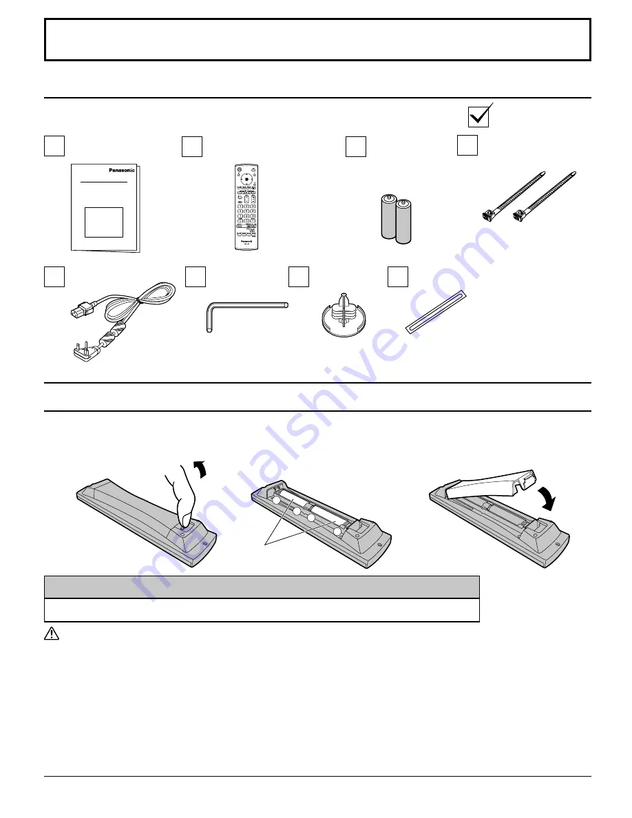
Accessories

Requires two AA batteries.

2.  Insert batteries - note correct 

polarity ( + and -).

  Precaution on battery use

Incorrect installation can cause battery leakage and corrosion that will damage the remote control transmitter.
Disposal of batteries should be in an environment-friendly manner.

Observe the following precautions:

1. Batteries should always be replaced as a pair. Always use new batteries when replacing the old set.
2. Do not combine a used battery with a new one.
3. Do not mix battery types (example: “Zinc Carbon” with “Alkaline”).
4. Do not attempt to charge, short-circuit, disassemble, heat or burn used batteries.
5. Battery replacement is necessary when the remote control acts sporadically or stops operating the Plasma Display.
6. Do not burn or breakup batteries.
    Batteries must not be exposed to excessive heat such as sunshine, 

fi

 re or the like.

3. Replace the cover.

Accessories Supplied

Check that you have the Accessories and items shown

Operating
Instruction book

Remote Control Transmitter
EUR7636070R

Batteries for the 
Remote Control 
Transmitter
(AA Size × 2)

AC cord

Fixing bands × 2

Remote Control Batteries

“AA” size

Helpful Hint:

For frequent remote control users, replace old batteries with Alkaline batteries for longer life.

1.  Pull and hold the hook, then 

open the battery cover.

Allen wrench

Eyebolt cap × 3

Blind sheet × 1

Содержание TH-103PF12U

Страница 1: ...justing this product please read these instructions completely Please keep this manual for future reference English The illustration shown is an image TQBC2518 Operating Instructions High Definition Plasma Display TH 103PF12U Model No ...

Страница 2: ...DO NOT OPEN WARNING To prevent damage which may result in fire or shock hazard do not expose this apparatus to rain or moisture Do not place containers with water flower vase cups cosmetics etc above the set including on shelves above etc WARNING 1 To prevent electric shock do not remove cover No user serviceable parts inside Refer servicing to qualified service personnel 2 Do not remove the groun...

Страница 3: ...ent of the obsolete outlet 10 Protect the power cord from being walked on or pinched particularly at plugs convenience receptacles and the point where they exit from the apparatus 11 Only use attachments accessories specified by the manufacturer 12 Use only with the cart stand tripod bracket or table specified by the manufacturer or sold with the apparatus When a cart is used use caution when movi...

Страница 4: ...VANCED SETTINGS 29 Picture Profiles 30 Saving profiles 31 Loading profiles 32 Editing profiles 32 Locking profiles 33 SOUND Adjustment 35 SDI SOUND OUTPUT 35 PRESENT TIME SETUP SET UP TIMER 36 PRESENT TIME SETUP 36 SET UP TIMER 36 SCREENSAVER For preventing image retention 37 Setup of SCREENSAVER Time 38 Reduces screen image retention 39 EXTENDED LIFE SETTINGS 39 Reduces power consumption 42 Custo...

Страница 5: ...including interference that may cause undesired operation FCC CAUTION To assure continued compliance follow the attached installation instructions and use only shielded interface cables when connecting to computer or peripheral devices Any changes or modifications not expressly approved by Panasonic Corp of North America could void the user s authority to operate this device FCC Declaration of Con...

Страница 6: ...fore it may affect other infrared communication equipment Install your infrared sensor in a place away from direct or reflected light from your Plasma Display Note Do not allow a still picture to be displayed for an extended period as this can cause a permanent image retention to remain on the Plasma Display Examples of still pictures include logos video games computer images teletext and images d...

Страница 7: ... or more at the top left and right and 8 0 20 cm or more at the rear and also keep the space between the bottom of the display and the floor surface If using some other setting up method follow the manual of it If there is no specific indication of installation dimension in the installation manual leave a space of 12 0 30 cm or more at the top bottom left and right and 8 0 20 cm or more at the rea...

Страница 8: ... short circuit disassemble heat or burn used batteries 5 Battery replacement is necessary when the remote control acts sporadically or stops operating the Plasma Display 6 Do not burn or breakup batteries Batteries must not be exposed to excessive heat such as sunshine fire or the like 3 Replace the cover Accessories Supplied Check that you have the Accessories and items shown Operating Instructio...

Страница 9: ... Terminal boards are installed in SLOT 2 and SLOT 3 AUDIO OUT Terminals connection Stereophonic sound code audio equipment line in From SERIAL Terminal on Computer see page 11 From EXTERNAL monitor terminal on Computer see page 10 DualHDMITerminals equivalent of Dual HDMITerminalBoard TY FB10HMD see page 12 Optional Terminal Board Insert Slot covered COMPONENT RGB IN and AudioINTerminals equivalen...

Страница 10: ...mputer at the time of connection Some PC models cannot be connected to the set There is no need to use an adapter for computers with DOS V compatible Mini D sub 15P terminal The computer shown in the illustration is for example purposes only Additional equipment and cables shown are not supplied with this set Do not set the horizontal and vertical scanning frequencies for PC signals which are abov...

Страница 11: ...sure to wait for the response for the first command to come from this unit before sending the next command If an incorrect command is sent by mistake this unit will send an ER401 command back to the computer SL1A SL1B SL2AandSL2BofCommandIMSareavailable only when a dual input terminal board is attached Pin layout for SERIAL Terminal COMPUTER RS 232C Straight cable D sub 9p Command Command Paramete...

Страница 12: ...l Pin No Signal 1 T M D S Data2 11 T M D S Clock Shield 2 T M D S Data2 Shield 12 T M D S Clock 3 T M D S Data2 13 CEC 4 T M D S Data1 14 Reserved N C on device 5 T M D S Data1 Shield 6 T M D S Data1 15 SCL 7 T M D S Data0 16 SDA 8 T M D S Data0 Shield 17 DDC CEC Ground 9 T M D S Data0 18 5V Power 10 T M D S Clock 19 Hot Plug Detect COMPONENT RGB connection Notes Change the COMPONENT RGB IN SELECT...

Страница 13: ...lug at the socket outlet first Press the Power switch on the Plasma Display to turn the set on Power On Power Indicator Green Press the button on the remote control to turn the Plasma Display off Power Indicator Red standby Press the button on the remote control to turn the Plasma Display on Power Indicator Green Turn the power to the Plasma Display off by pressing the switch on the unit when the ...

Страница 14: ...on the unit Following screen will be displayed when the unit is turned on for the first time Select the items with the remote control Unit buttons are invalid OSD LANGUAGE PRESENT TIME SETUP DISPLAY ORIENTATION 1 Select the language 2 Set 1 Select DAY or PRESENT TIME OF DAY 2 Setup DAY or PRESENT TIME OF DAY 1 For vertical installation select PORTRAIT 2 Set Notes Once the items are set the screens...

Страница 15: ...terminals see page 50 In 2 screen display the same input mode cannot be selected for the main picture and sub picture Image retention image lag may occur on the plasma display panel when a still picture is kept on the panel for an extended period The function that darkens the screen slightly is activated to prevent image retention see page 60 but this function is not the perfect solution to image ...

Страница 16: ...spect button see page 18 23 INPUT button INPUT signal selection see page 15 Right side surface Power Indicator The Power Indicator will light Power OFF Indicator not illuminated The unit will still consume some power as long as the power cord is still inserted into the wall outlet Standby Red Orange When Slot power is set to On See page 57 Orange Depending on the type of the function board install...

Страница 17: ... 19 Status button Press the Status button to display the current system status 1 Input label 2 Aspect mode see page 18 NANODRIFT SAVER operating see page 40 3 Off timer The off timer indicator is displayed only when the off timer has been set 4 Clock display see page 57 R button see page 23 Press the R button to return to previous menu screen POSITION buttons ACTION button Press to make selections...

Страница 18: ...al Video Terminal Board TY FB9BD Panasonic AUTO cannot be selected Note Be aware that if you put the display in a public place for commercial purposes or a public showing and then use the aspect mode select function to shrink or expand the picture you may be violating the copyright under copyright law It is prohibited to show or alter the copyrighted materials of other people for commercial purpos...

Страница 19: ... MULTI PIP SETUP is changed see page 47 During PIP During Advanced PIP One screen Advanced PIP Main screen Sub screen 1 8 2 7 3 6 4 5 One screen Two screens P AND P Sub screen input mode Main screen input mode Two screens P OUT P Two screens P IN P Main screen Sub screen INPUT1 PC PC INPUT1 INPUT1 PC Note and button operations are not available during advanced PIP For SD signal input 525 480 60i 6...

Страница 20: ...ion and the insertion function Set these functions with TRANSPARENCY or INSERT in MULTI PIP SETUP see page 47 Transparent Function Data such as text are displayed transparently on the background image Insertion Function The sub screen image is divided into transparent and non transparent areas and only the non transparent areas are inserted and displayed on the background image Note Be aware that ...

Страница 21: ... permanent image retention to remain on the screen If INPUT lock in Options menu is set to other than Off MULTI PIP function isn t available Sound output is from the picture which is selected in AUDIO OUT PIP see page 35 In two screen display the same input mode cannot be selected for the main picture and sub picture The main picture and sub picture are processed by different circuits resulting in...

Страница 22: ...ital Zoom function cannot be selected while in the following operation state Multi viewer P AND P P OUT P P IN P operation see page 19 When MULTI DISPLAY SETUP is ON see page 45 When PORTRAIT SETUP is ON see page 48 When SCREENSAVER except for NEGATIVE IMAGE is running see page 37 While Digital Zoom is in operation Adjusting POS SIZE cannot be used Select the magnification required for the enlarge...

Страница 23: ...iewing PICTURE SOUND POS SIZE SET UP 2 Select the item Select VOL ENTER Press Select 25 0 0 0 5 PICTURE NORMAL NORMALIZE STANDARD BRIGHTNESS SHARPNESS PICTURE MENU COLOR PICTURE TINT COLOR MANAGEMENT ADVANCED SETTINGS MEMORY SAVE COLOR TEMP NORMAL OFF MEMORY LOAD MEMORY EDIT Example PICTURE menu 3 Set Set VOL ENTER Press Set 4 Exit the menu Press Press to return to the previous menu MENU Press sev...

Страница 24: ...5 27 see page 35 see page 36 54 2 2 SOUND OUT LEFT CHANNEL RIGHT CHANNEL CHANNEL 1 CHANNEL 1 OFF LEVEL METER OFF SDI SOUND OUTPUT 0 0 0 1 2 SOUND NORMAL NORMALIZE OFF TREBLE BALANCE BASS 0 MID SURROUND MAIN AUDIO OUT PIP 3D Y C FILTER NTSC COLOR SYSTEM SIGNAL ON 3 2 PULLDOWN Panasonic AUTO 4 3 VIDEO NOISE REDUCTION REFRESH RATE AUTO OFF 4 3 OFF 100 Hz see page 51 54 SCREENSAVER START FUNCTION MODE...

Страница 25: ...c AUTO with FULL mode the adjustment is not memorized When exiting the mode the screen will return to a former adjustment 2 3 4 AUTO SETUP H POS V POS H SIZE V SIZE DOT CLOCK and CLOCK PHASE are automatically adjusted when the RGB or PC signal is received This setting is enabled under the following conditions This setting only support single screen display Two screen display or multiple display ar...

Страница 26: ... 162 MHz or higher DOT CLOCK and CLOCK PHASE cannot be made When digital RGB signal input DOT CLOCK and CLOCK PHASE cannot be made AUTO SETUP may not work when a cropped or dark image is input In such case switch to a bright image with borders and other objects are clearly shown and then try auto setup again Depending on the signal out of alignment may occur after AUTO SETUP Carry out fine tuning ...

Страница 27: ... input Notes Select ON when you would like to replay 1920 1080 input signal Applicable input signal 1125 1080 50i 60i 24sF 24p 25p 30p 50p 60p 1250 1080 50i Select OFF when flickering is shown around the image H SIZE and V SIZE cannot be adjusted when ON is selected OFF ON 1 1 PIXEL MODE 2k1k For 2k1k signals When the input signal is a 2k1k signal 2048 1080 24p 2048 1080 24sF the display size is a...

Страница 28: ...ignal input and menu setting 2 Press the left or right button to switch between modes MONITOR STANDARD CINEMA DYNAMIC STANDARD For viewing in standard evening lighting environments This menu selects the normal levels of BRIGHTNESS and PICTURE DYNAMIC For viewing in brighter environments This menu selects higher than normal levels of BRIGHTNESS and PICTURE CINEMA Ideal for movies MONITOR For use wh...

Страница 29: ...ion INPUT LEVEL Less More Adjustment of parts which are extremely bright and hard to see GAMMA Down Up S CURVE 1 S CURVE 2 0 2 2 2 5 2 6 2 1 When PICTURE MENU is set to DYNAMIC GAMMA S CURVE can be selected When 2k1k signals are received with the Dual Link HD SDI Terminal Board TY FB11DHD S CURVE cannot be selected 2 When 2k1k signals are received with the Dual Link HD SDI Terminal Board TY FB11DH...

Страница 30: ...LOR TEMP NORMAL OFF Options On Weekly Command Timer Onscreen display Memory lock Off Initial INPUT Initial VOL level 1 3 Off Off 0 0 Maximum VOL level Off INPUT lock Off Button lock Off Remocon User level 30 Picture Profiles Up to 8 combinations of picture adjustment values in the PICTURE menu and ADVANCED SETTINGS can be stored in the display memory as profiles and applied as needed for a conveni...

Страница 31: ...2 set 5 Enter a name for the profile Entering profile names Profile names can be up to 16 characters To enter text select characters in the on screen keyboard Edit the default profile name in the text box as desired MEMORY NAME INPUT OK A MEMORY1 B C D E F G H I J K L M ALL DELETE N O P Q R S T U V W X Y Z DELETE SPACE a b c d e f g h i j k l m n o p q r s t u v w x y z 0 1 2 3 4 5 6 7 8 9 _ ˆ CAN...

Страница 32: ... profile to delete To delete all profiles select ALL DELETE MEMORY DELETE ALL DELETE 1 2 3 MEMORY2 MEMORY3 MEMORY1 1 select 2 set 4 Select OK MEMORY DELETE CANCEL DELETE THE MEMORY1 DATA OK 1 select 2 set 1 In the PICTURE menu select MEMORY EDIT MEMORY SAVE MEMORY LOAD MEMORY EDIT 1 select 2 access 2 Select MEMORY NAME CHANGE MEMORY EDIT MEMORY NAME CHANGE MEMORY DELETE 1 select 2 set 3 Select the...

Страница 33: ...0 5 PICTURE NORMAL NORMALIZE STANDARD BRIGHTNESS SHARPNESS PICTURE MENU COLOR PICTURE TINT COLOR MANAGEMENT ADVANCED SETTINGS COLOR TEMP NORMAL OFF Can be specified Cannot be specified PICTURE NORMAL NORMALIZE STANDARD BRIGHTNESS SHARPNESS PICTURE MENU COLOR PICTURE TINT COLOR MANAGEMENT ADVANCED SETTINGS COLOR TEMP Can be specified Cannot be specified Locking profiles Loading locked profiles In t...

Страница 34: ...et 5 Exit the menu isf Mode Setting Switches to PICTURE MENU mode display 1 Follow steps 1 4 in the previous procedure Locking and unlocking profiles 2 Select isf Mode Memory lock Off Change password MEMORY3 Off MEMORY4 Lock1 MEMORY1 Off MEMORY2 isf Mode Off 1 select 2 adjust 3 Specify On or Off 4 Exit the menu Specifying On for isf Mode changes the PICTURE MENU mode display as follows PICTURE MEN...

Страница 35: ...electing a slot that HD SDI Terminal Board with audio TY FB10HD or Dual Link HD SDI Terminal Board TY FB11DHD is installed This menu is unavailable when 2 picture display mode is active Item Details LEFT CHANNEL CHANNEL 1 to CHANNEL 16 Selects left audio channel RIGHT CHANNEL CHANNEL 1 to CHANNEL 16 Selects right audio channel SOUND OUT ON OFF ON Enables audio output OFF Disables audio output LEVE...

Страница 36: ...utton Back Notes Pressing or button once changes PRESENT TIME OF DAY 1 minute Pressing or button continuously changes PRESENT TIME OF DAY by 15 minutes Press to select SET Press to store PRESENT TIME SETUP Notes SET cannot be selected unless PRESENT TIME OF DAY is set Unless setting the present time other than 99 99 DAY setting is invalid The settings of DAY and PRESENT TIME OF DAY are reset when ...

Страница 37: ...sappear and the SCREENSAVER will be activated To stop the SCREENSAVER under ON press the R button or any buttons on the main unit Note When the display is turned off the SCREENSAVER will be deactivated Press to select the MODE Press to select each mode items SCREENSAVER For preventing image retention Off INTERVAL Operates when SHOW DURATION and SAVER DURATION are set up and those times arrive TIME...

Страница 38: ...or selection and the Operating Time may be set Time cannot be set when MODE is ON or OFF Press to select START TIME FINISH TIME when TIME OF DAY is selected Press to select SHOW DURATION SAVER DURATION when INTERVAL is selected Press to select SCREENSAVER DURATION when STANDBY AFTER SCR SAVER is selected Press to setup button Forward button Back Note Timer function will not work unless PRESENT TIM...

Страница 39: ... may be applicable to the non picture area OFF Darken both ends DARK Make it dark gray MID Make it gray BRIGHT Make it light gray Notes To reduce the occurrence of image retention set the SIDE BAR ADJUST to BRIGHT The side bar may flash alternate black white depending on the picture being shown on the screen Using Cinema mode will reduce such flashing side bars 4 3 mode image retention P OUT P P A...

Страница 40: ...DRIFT SAVER operates The display position of the screen moves at set time intervals You can set the screen movement range Some of the screen may appear to be missing as a result of this operation If you change the value a mask is displayed in the range where the picture is missing as a result of position movement If this is set to other than OFF NANODRIFT is displayed below the aspect mode display...

Страница 41: ...30 RECOMMENDED SETTINGS 1 select 2 adjust Whenamenuislocked itisgrayedoutandcannotbeset PICTURE MENU and PICTURE will no longer be able to set in the PICTURE menu and they are labeled with icon to indicate their locked status Also NORMALIZE MEMORY SAVE and MEMORY LOAD are not available 0 0 0 5 PICTURE NORMAL NORMALIZE DYNAMIC BRIGHTNESS SHARPNESS PICTURE MENU COLOR PICTURE TINT COLOR MANAGEMENT AD...

Страница 42: ...rates under the following conditions to turn the power on or off automatically When no pictures HD VD sync signals are detected for 30 or so seconds during PC signal input Power is turned off standby the power indicator lights up orange When pictures HD VD sync signals are subsequently detected Power is turned on the power indicator lights up green Notes This function operates only during PC signa...

Страница 43: ...inal Board connected to Slot 1 Slot 2 and Slot 3 the Input label will depend on each Optional Terminal Board INPUT LABELS for SLOT 1 2 3 and PC IN SLOT1 INPUT1 DVD1 DVD2 DVD3 Blu ray1 Blu ray2 Blu ray3 CATV VCR STB SLOT2 INPUT2 DVD1 DVD2 DVD3 Blu ray1 Blu ray2 Blu ray3 CATV VCR STB SLOT3 INPUT3 DVD1 DVD2 DVD3 Blu ray1 Blu ray2 Blu ray3 CATV VCR STB PC IN PC DVD1 DVD2 DVD3 Blu ray1 Blu ray2 Blu ray...

Страница 44: ...stalled vertically the power switch should be located at the bottom Fan control will be switched when turning on the unit next time LANDSCAPE PORTRAIT Fan control for horizontal installation Fan control for vertical installation On screen menu will be rotated 90 degrees counterclockwise to be suitable for the setting DISPLAY ORIENTATION 2 2 SET UP MULTI DISPLAY SETUP SET UP TIMER PRESENT TIME SETU...

Страница 45: ...ULTI DISPLAY group of 16 4 4 group of 4 2 2 group of 9 3 3 SET UP for MULTI DISPLAY Example group of 25 5 5 Press to display the SET UP menu 1 2 3 Press to select the MULTI DISPLAY SETUP Press to select ON or OFF Item Details MULTI DISPLAY SETUP Select ON or OFF Note If you set MULTI DISPLAY SETUP to ON PORTRAIT SETUP will be unavailable HORIZONTAL SCALE Select 1 2 3 4 5 VERTICAL SCALE Select 1 2 ...

Страница 46: ...mote ID On to operate the ID remote control If remote ID is set to On you can use the remote control without identical ID number during option menu display see page 56 The ID remote control cannot be used when ID select is set to anything other than 0 and the remote control ID is not the same as the ID select number see page 56 ID remote control button operation The operation is the same as normal...

Страница 47: ...age to insert sub screen INSERT LEVEL Background image main screen Two picture insertion Onlytheareasontheoverlay image that are brighter than the INSERT LEVEL are displayedonthebackground image 10 1 Note TRANSPARENCY cannot be set when INSERT is ON Transparent Display of the Sub Screen During BLEND PIP 1 Select ON in TRANSPARENCY 2 Set the transparency level for the sub screen in TRANSPARENCY LEV...

Страница 48: ...O Press to select OFF ON How to setup PORTRAIT 1 2 3 4 To hide joints between displays Suitable for moving image display To show joints between displays Suitable for still image display ON OFF 2 2 SET UP MULTI DISPLAY SETUP SET UP TIMER PRESENT TIME SETUP DISPLAY ORIENTATION LANDSCAPE MULTI PIP SETUP PORTRAIT SETUP OFF PORTRAIT SETUP SEAM HIDES VIDEO OFF 1 OFF AI SYNCHRONIZATION VIEWING AREA LOCAT...

Страница 49: ...RONIZATION VIEWING AREA LOCATION 16 9 PORTRAIT SETUP OFF PORTRAIT SETUP SEAM HIDES VIDEO OFF 1 OFF AI SYNCHRONIZATION VIEWING AREA LOCATION 16 9 PORTRAIT SETUP 5 VIEWING AREA Set a mode of image division for PORTRAIT function LOCATION Set a location of image to be displayed for PORTRAIT function VIEWING AREA LOCATION When PORTRAIT SETUP ON Display the image of the selected LOCATION When PORTRAIT S...

Страница 50: ...B signals RGB Press to display the SET UP menu Press to select the COMPONENT RGB IN SELECT Press to select the desired mode COMPONENT RGB Press to exit from adjust mode Notes Selection may not be possible depending on which optional board is installed Make setting of the selected input terminal SLOT1 SLOT2 SLOT3 or PC IN 1 2 3 YUV RGB IN SELECT Select to match the signals from the source connected...

Страница 51: ...1024 60 SYNC SIGNAL H FREQ V FREQ kHz Hz 63 98 60 02 SIGNAL FORMAT 1280 1024 60 RGB 3 2 PULLDOWN XGA MODE NOISE REDUCTION OFF REFRESH RATE 100 Hz AUTO OFF AUTO 3D Y C FILTER NTSC ON 51 Press to select the menu to adjust Press to adjust the menu Press to exit from adjust mode Note SIGNAL setup menu displays a different setting condition for each input signal 3 4 SET UP for Input Signals SIGNAL menu...

Страница 52: ...tem to match the input signal When selecting AUTO the color system is automatically selected from NTSC PAL SECAM however M NTSC signal is not displayed properly depending on the attached terminal board To display M NTSC signal select M NTSC in COLOR SYSTEM To display PAL60 signal select PAL when BNC Dual Video Terminal Board TY FB9BD is used For other Video Terminal Boards select M NTSC AUTO SECAM...

Страница 53: ...is being applied REFRESH RATE SET UP for Input Signals Press to select REFRESH RATE Press to adjust This function sets the refresh rate of the display This menu is displayed when the input signal is 50 Hz system 50i 50p 25p 24p 24sF of vertical scan rate 100 Hz Reduce screen flicker 50 Hz Enhance the resolution of moving images Note It is recommended to set to 100 Hz normally NOISE REDUCTION Sets ...

Страница 54: ... ON G Uses a synchronized signal on the Video G signal which is input from the G connector VBS Uses a synchronized signal of Composite Sync input which is input from the HD connector Displays the frequency and the type of the current input signal This display is valid only for COMPONENT RGB PC and Digital input signal Display range Horizontal 15 110 kHz Vertical 48 120 Hz The dot clock frequency i...

Страница 55: ...ut terminal board is attached A or B is displayed depending on the selected input signal Ex INPUT1A INPUT1B Initial VOL level Press button to adjust the volume when the unit is turned on Off On Off Sets normal volume On Sets your preferred volume Notes When Maximum VOL level is On the volume can only be adjusted between 0 and your maximum range You can hear the changed volume regardless of your vo...

Страница 56: ...from failure or after plugging off and in again Normal Power returns in as the same state as before the power interruption Standby Power returns in standby mode Power Indicator red orange On Power returns in power On Power Indicator green Note When using multiple displays Standby is preferred to be set in order to reduce a power load ID select Sets panel ID number when panel is used in Remote ID o...

Страница 57: ...ower to the board with time delay according to the setting The power indicator lights up red first and it turns orange when the power starts being supplied to the board Clock Display Off Not display the clock On Display the clock The clock is displayed at the lower left of the screen when button is pressed Note When PRESENT TIME SETUP is not set the clock is not displayed even if Clock Display is ...

Страница 58: ...set 7 day timer programming by setting time and command Note Before setting Weekly Command Timer set PRESENT TIME SETUP see page 36 Press to select Function Press to select On Note When Function is set to On SET UP TIMER see page 36 is unavailable and INTERVAL TIME OF DAY in MODE of SCREENSAVER see page 37 cannot be selected 1 Press to select a day Press to select a program number Note You can set...

Страница 59: ...utton to select OSD LANGUAGE 3 Press and hold the ENTER button till the Shipping menu is displayed 4 Press the Volume Up or Down button to select YES 5 Press the ENTER button and wait for 10 sec Options Adjustments Press to select Command No Press to select a command number 6 Press to select Time Command Press to set each item Time Set the time to execute a command program Pressing or button once ...

Страница 60: ...r between image and audio depending on the type of input signal However this is not a malfunction Plasma Display panel Symptoms Check The screen darkens slightly when bright pictures with minimal movements are shown The screen will darken slightly when photos still images of a computer or other pictures with minimal movements are shown for an extended period This is done to reduce image retention ...

Страница 61: ...e areas around the left and right edges of the screen is slightly elongated 4 3 4 3 Pictures with a 4 3 aspect ratio are displayed with their original aspect ratio Side panels are displayed at the left and right edges of the screen 4 3 1 4 3 2 4 3 Pictures with a 4 3 aspect ratio are displayed with their original aspect ratio The left and right edges of the pictures are masked by side panels 4 3 F...

Страница 62: ...5 0 32 1 024 768 70 Hz 56 48 70 07 75 0 33 1 024 768 75 Hz 60 02 75 03 78 75 34 1 024 768 85 Hz 68 68 85 00 94 5 35 1 066 600 60 Hz 37 64 59 94 53 0 53 0 36 1 152 864 60 Hz 53 70 60 00 81 62 37 1 152 864 75 Hz 67 50 75 00 108 0 38 1 280 768 60 Hz 47 70 60 00 80 14 39 1 280 960 60 Hz 60 00 60 00 108 0 40 1 280 960 85 Hz 85 94 85 00 148 5 41 1 280 1 024 60 Hz 63 98 60 02 108 0 108 0 42 1 280 1 024 7...

Страница 63: ...25 50p 50 00 31 25 27 00 720 864 576 625 4 750 60p 60 00 45 00 74 25 1280 1650 720 750 5 750 50p 50 00 37 50 74 25 1280 1980 720 750 6 1125 60i 60 00 33 75 74 25 1920 2200 1080 1125 7 1125 50i 50 00 28 13 74 25 1920 2640 1080 1125 8 1125 60p 60 00 67 50 148 50 1920 2200 1080 1125 9 1125 50p 50 00 56 26 148 50 1920 2640 1080 1125 10 1125 24p 24 00 27 00 74 25 1920 2750 1080 1125 VIDEO input HDMI No...

Страница 64: ... DWA POP Dual Picture mode Picture out Picture 37 DWA SWP Swap main picture and sub picture when PIP mode 38 DWA TWN Dual Picture mode Picture and Picture 39 IMS PC1 Input select PC1 Main Picture when PIP mode 40 IMS SL1 Input select SLOT1 Main Picture when PIP mode 41 IMS SL1A Input select SLOT1A Main Picture when PIP mode 42 IMS SL1B Input select SLOT1B Main Picture when PIP mode 43 IMS SL2 Inpu...

Страница 65: ...quency 48 120 Hz Connection terminals HDMI A B TYPE A Connector 2 COMPONENT RGB IN Y G BNC PB B BNC PR R BNC AUDIO IN RCA PIN JACK 2 with sync 1 0 Vp p 75 Ω 0 7 Vp p 75 Ω 0 5 Vrms PC IN HIGH DENSITY MINI D SUB 15PIN B PB CB R PR CR HD VD AUDIO IN M3 JACK Y or G with sync 1 0 Vp p 75 Ω Y or G without sync 0 7 Vp p 75 Ω 0 7 Vp p 75 Ω 0 7 Vp p 75 Ω 1 0 5 0 Vp p high impedance 0 5 Vrms SERIAL EXTERNAL...

Страница 66: ...s indicated above Panasonic Professional Display Company referred to as the Warrantor will repair this product and all included accessories with new or refurbished parts free of charge in the USA or Puerto Rico of the original purchase in the event of a defect in materials or workmanship as follows In the USA and Puerto Rico FOR SERVICE CALL TOLL FREE 1 800 973 4390 3 Years 3 Years On site or carr...

Страница 67: ...rage period Proof of product purchase is a condition of warranty service The owner must produce the product purchase receipt or other satisfactory evidence of date of original purchase This warranty does not apply to external appearance items such as handles knobs safety windows etc This warranty does not apply to any part or parts of the product installed altered repaired or misused in any way th...

Страница 68: ...68 ...

Страница 69: ...69 Memo ...

Страница 70: ...70 Memo ...

Страница 71: ...71 Memo ...

Страница 72: ...W 2T3 Customer s Record The model number and serial number of this product can be found on its back cover You should note this serial number in the space provided below and retain this book plus your purchase receipt as a permanent record of your purchase to aid in identification in the event of theft or loss and for Warranty Service purposes Model Number Serial Number Panasonic Corporation 2009 P...

Отзывы: