20
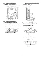
7.13. Remove the SS-Board
1. Remove the Tuner unit. (See section 7.4.)
2. Unlock the cable clampers to free the cable.
3. Disconnect the connectors (SS3, SS11 and SS23).
4. Disconnect the flexible cables (SS52 and SS55).
5. Disconnect the bridge connector (SS22-SS24).
6. Remove the screws (
×
5
) and remove the SS-Board.
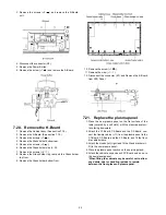
7.14. Remove the Hanger metals and
the Stand brackets
1. Remove the Plasma panel section from the servicing
stand and lay on a flat surface such as a table (covered)
with the Plasma panel surface facing downward.
2. Remove the Hanger metals (L, R) fastening screws (
×
4
each) and remove the Hanger metals (L, R).
3. Remove the Stand brackets (L, R) fastening screws (
×
4
each) and remove the Stand bracket metals (L, R)
and the Stand brackets (L, R).
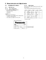
7.15. Remove the C1-Board
1. Remove the Control button unit. (See section 7.7.)
2. Remove the flexible cables holder fastening screws (
×
6
).
3. Disconnect the flexible cables (CB1, CB2 and CB3).
4. Disconnect the flexible cable (C10).
5. Disconnect the connector (C14).
6. Remove the screws (
×
3
) and remove the C1-Board.
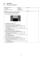
7.16. Remove the C2-Board
1. Remove the Hanger metal R and the Stand bracket R.
(See section 7.14.)
2. Remove the flexible cables holder fastening screws (
×
8
).
3. Disconnect the flexible cables (CB4, CB5, CB6 and CB7).
4. Disconnect the flexible cables (C20, C21 and C22).
5. Remove the screws (
×
4
) and remove the C2-Board.
Содержание TC-P50X1
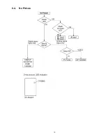
Страница 15: ...15 6 4 No Picture ...
Страница 25: ...25 8 1 4 Adjustment Volume Location 8 1 5 Test Point Location ...
Страница 27: ...27 ...
Страница 28: ...28 ...
Страница 34: ...34 10 3 Wiring 2 ...
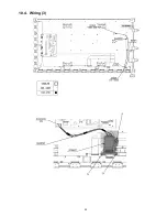
Страница 35: ...35 10 4 Wiring 3 ...
Страница 36: ...36 10 5 Wiring 4 ...
Страница 37: ...37 11 Schematic Diagram 11 1 Schematic Diagram Note ...
Страница 67: ...67 12 Printed Circuit Board 12 1 P Board A B C D E F G H I 1 2 3 4 5 6 P BOARD FOIL SIDE LSEP1279UNHB ...
Страница 69: ...69 A B C D E F G H I 1 2 3 4 5 6 P BOARD COMPONENT SIDE LSEP1279UNHB ...
Страница 82: ...82 ...
Страница 84: ...84 13 1 2 Accessories ...
Страница 85: ...85 13 1 3 Mechanical Replacement Parts List ...
Страница 88: ...88 13 2 Electrical Replacement Parts List 13 2 1 Replacement Parts List Notes ...

