


17
7 Disassembly and Assembly Instructions
7.1.
Remove the Rear cover
1. See Service Hint (Section 3)
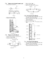
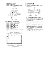
7.2.
Remove the Fan
1. Unlock the cable clampers to free the cable.
2. Remove the screws (
×
3 ).
3. Remove the relay connectors and remove the Fan unit.
4. Remove the screw (
×
1
) on the back side.
5. Remove the Fan.
7.3.
Remove the P-Board
Caution:
To remove P.C.B. wait 1 minute after power was off for dis-
charge from electrolysis capacitors.
1. Unlock the cable clampers to free the cable
2. Disconnect the connectors (P2, P6, P7, P9, P11, P25 and
P35).
3. Remove the screws (
×
9
) and remove the P-Board.
7.4.
Remove the Side terminal
cover and Rear terminal cover
1. Remove the claw (
×
1 ).
2. Remove the Side terminal cover.
Содержание TC-P50S1
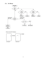
Страница 15: ...15 6 4 No Picture ...
Страница 26: ...26 8 1 4 Adjustment Volume Location 8 1 5 Test Point Location ...
Страница 28: ...28 ...
Страница 34: ...34 ...
Страница 36: ...36 10 3 Wiring 2 ...
Страница 37: ...37 10 4 Wiring 3 ...
Страница 38: ...38 10 5 Wiring 4 ...
Страница 39: ...39 10 6 Wiring 5 ...
Страница 40: ...40 ...
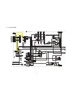
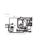
Страница 41: ...41 11 Schematic Diagram 11 1 Schematic Diagram Note ...
Страница 71: ...71 12 Printed Circuit Board 12 1 P Board A B C D E F G H I 1 2 3 4 5 6 P BOARD FOIL SIDE ETX2MM747AFK ...
Страница 73: ...73 A B C D E F G H I 1 2 3 4 5 6 P BOARD COMPONENT SIDE ETX2MM747AFK ...
Страница 86: ...86 ...
Страница 88: ...88 13 1 2 Accessories ...
Страница 89: ...89 13 1 3 Mechanical Replacement Parts List ...
Страница 92: ...92 13 2 Electrical Replacement Parts List 13 2 1 Replacement Parts List Notes ...


